DISASSEMBLING PROCEDURE CLV-160
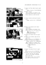
(2) Remove the lamp housing.
Phillips screwdriver No.2 (CCUK3x6SZ x 4)
(When assembling, tighten the screws as
specified on the left.)
(3) Remove the screws, and remove the S-
socket from the optical base.
Phillips screwdriver No.2(CCUK4x12SZ x 4)
(4) Remove the cable holder from the optical
base.
Box screwdriver(5.5mm)(C6N3SZ x 3)
(5) Remove the turret unit from the optical
base.
Phillips screwdriver No.2 (CCUK3x6SZ x 3)
(When assembling, tighten the screw A
together with the earth strap as shown on
the left. For forming of the emergency lamp
harness, see the drawing below.)
Cable holder
Emergency lamp harness
Turret
Optical
path
Limit
switch
Optical
base
View from the top
(6) Remove the lens holder and the diaphragm
unit from the optical base.
(The
diaphragm unit is located underside.)
Phillips screwdriver No.2 (CCUK3x6SZ x 2)
5-6
Summary of Contents for CLV-160
Page 1: ...MAINTENANCE MANUAL CLV 160...
Page 8: ...2 C O N N E C T I O N D I A G R A M 2 1...
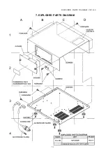
Page 45: ...EXPLODED PARTS DIAGRAM CLV 160 7 EXPLODED PARTS DIAGRAM 7 1...
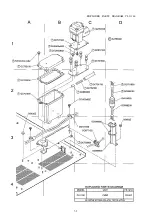
Page 46: ...EXPLODED PARTS DIAGRAM CLV 160 7 2...
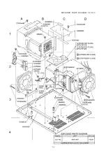
Page 47: ...EXPLODED PARTS DIAGRAM CLV 160 7 3...
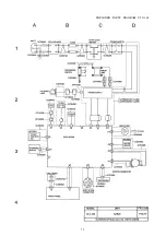
Page 48: ...EXPLODED PARTS DIAGRAM CLV 160 7 4...
Page 49: ...EXPLODED PARTS DIAGRAM CLV 160 7 5...
Page 50: ...EXPLODED PARTS DIAGRAM CLV 160 7 6...

