ASSEMBLING PROCEDURE CLV-160
6. ASSEMBLING PROCEDURE
1.
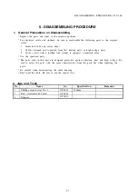
General Precautions on Assembling
Replace the parts and wires to the original positions.
For electrical safety and standard, be sure to reassemble the following parts to the original
states.
1.
Insulation tube and mylar sheet
2.
Cables clamped and separated from the heating parts or high-voltage parts
3 .
Cover screws with a toothed lock washer to suppress a radiation noise
Use the specified parts.
The parts used in this unit are designed protective against vibration, heat and high voltage. Be
sure to select the parts with the same characteristics from the parts list when replacing the
p a r t s .
Be careful when disconnecting the cable housing.
Don’t pull the cable. Be sure to use the special tool.
Be careful not to be injured.
Some metallic parts have sharp corner or edge. Be careful when handling such parts.
Be sure to observe the specified torque and dimensions.
Observe the torque and dimensions when they are specified.
As for the H-band which secures each tube, first tighten it by the specified torque and then pull
the tube to check whether the tube becomes loose or it comes off.
Clean the parts to be used.
When re-using the same parts, eliminate the sealing material and tape and clean. For the O-ring
and packing, clean the surface of the parts on which the O-ring or packing is mounted.
Otherwise, it may cause water leakage.
Don’t forget to tighten the screws and nuts.
Failure in tightening the screws and nuts may cause water leakage.
2. Jigs and Tools
No
N a m e
1
Phillips screwdriver No. 2
No.
Specification
OT0287
150 mm
Remarks
3. Assembling Procedure
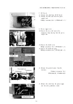
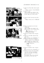
Reverse the disassembling procedure.
ISSUE1
6-1
Summary of Contents for CLV-160
Page 1: ...MAINTENANCE MANUAL CLV 160...
Page 8: ...2 C O N N E C T I O N D I A G R A M 2 1...
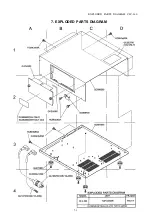
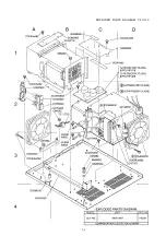
Page 45: ...EXPLODED PARTS DIAGRAM CLV 160 7 EXPLODED PARTS DIAGRAM 7 1...
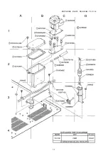
Page 46: ...EXPLODED PARTS DIAGRAM CLV 160 7 2...
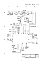
Page 47: ...EXPLODED PARTS DIAGRAM CLV 160 7 3...
Page 48: ...EXPLODED PARTS DIAGRAM CLV 160 7 4...
Page 49: ...EXPLODED PARTS DIAGRAM CLV 160 7 5...
Page 50: ...EXPLODED PARTS DIAGRAM CLV 160 7 6...

