4.4.4 Carrier and Platen Position Adjustment
Check:
There must be no missing parts of characters when printing, and
the intensity of the top and bottom halves of printed characters
must be equal.
Adjustment:
1) Enter adjustment mode. (Refer to 4.3.3 "Carrier and Platen
Position Adjustment Mode".) (Adjust the printing impression so
that characters are printed faintly on the paper (so that they can
be checked).)
2) Print vertical lines and underlines (or any characters with width
or height.)
3) Insert a flathead screwdriver into the rail slide hole (1-A) and
adjust the rail slide (2) position so that there are no missing
parts of characters and so that the top and bottom halves of the
characters are printed with even intensity.
If the top halves of characters are faint:
Move the rail slide (2) up.
If the bottom halves of characters are faint:
Move the rail slide (2) down.
4) Confirm that all characters are printed and that the intensity of
the top and bottom halves of the characters is even.
5) Turn the power switch off and leave adjustment mode.
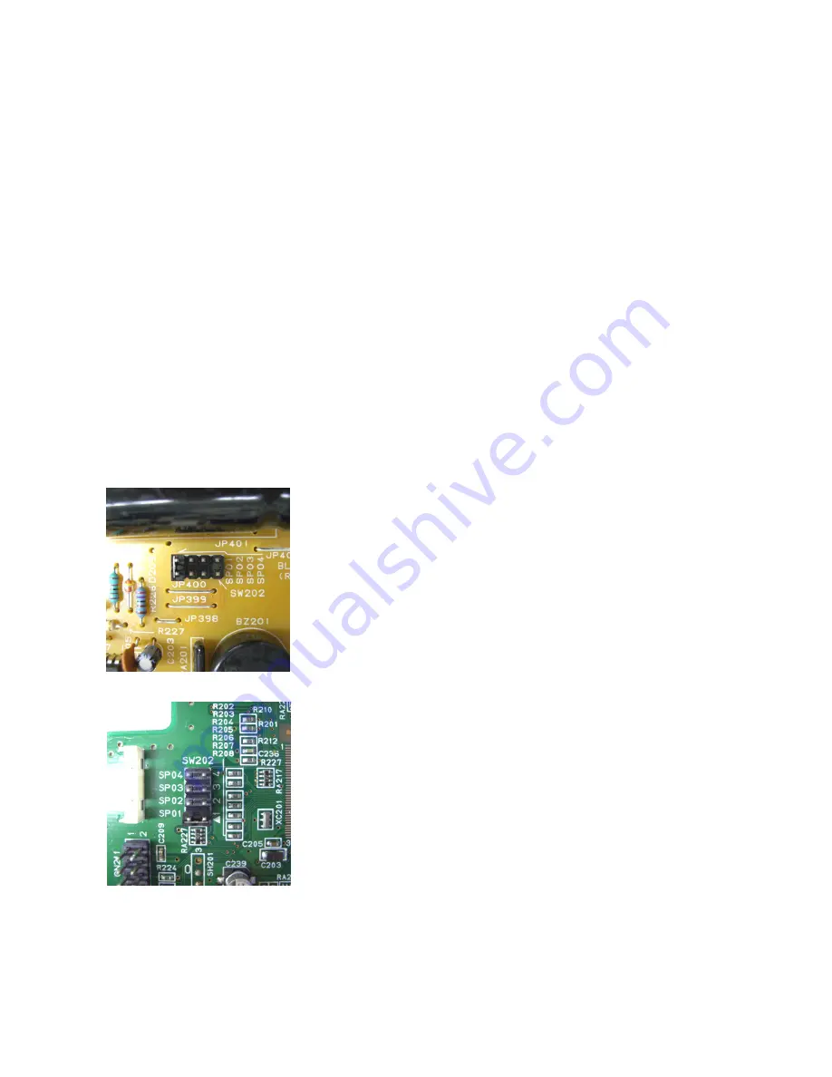
Original version PCB (999-32300)
The printing impression is returned to the factory (initial) setting.
If the printing impression is not appropriate, change the short pin
connection for SW202 on the control PCB. The printing
impression can be changed through the software.
Short pin
Open SP01 SP02 SP03 SP04
Printing impression Weak <- Standard -> Heavy
(The photos are setting that SP01 short-circuits.)
Note:
If the intensity of the top and bottom halves of characters can
not be made even, move the adjustment plates (3) located on
the left and right sides of the carrier box.
If the top halves of characters are faint:
Move the adjustment plates (3) down.
2nd version PCB (999-35810)
If the bottom halves of characters are faint:
Move the adjustment plates (3) up.
Confirmation:
Perform the self printing test or print vertical lines and confirm that
the intensity of the top and bottom halves of characters is even.
Possible symptoms:
Missing parts of characters, loss of detail, incomplete correction.
4-8
Summary of Contents for Carrera De Luxe MD
Page 14: ...3 2 Keyboard Keyboard layout Keyboard contact layout membrane sheet 3 3 ...
Page 15: ...Keyboard contact diagram keyboard matrix 3 4 ...
Page 19: ...3 5 LCD LCD layout Epson ECM A0697 type JIC MSBZ9129 type 3 8 ...
Page 20: ...LCD block diagram Epson ECM A0697 type JIC MSBZ9129 type 3 9 ...
Page 21: ...3 6 Control PCB Control PCB layout Original version Control PCB Artwork No 999 32300 3 10 ...
Page 22: ...2nd version Control PCB Artwork No 999 35810 3 11 ...
Page 23: ...3 12 Control PCB diagram Original version Control PCB Artwork No 999 32300 ...
Page 24: ...2nd version Control PCB Artwork No 999 35810 Page 1 3 3 13 ...
Page 25: ...2nd version Control PCB Artwork No 999 35810 Page 2 3 3 14 ...
Page 26: ...3 15 2nd version Control PCB Artwork No 999 35810 Page 3 3 ...
Page 30: ...4 4 ...
Page 37: ...Correction tape Ribbon tape 4 11 ...
Page 42: ...5 3 ...
Page 45: ...5 6 ...
Page 47: ...Original version Control PCB Artwork No 999 32300 5 8 ...
Page 48: ...2nd version Control PCB Artwork No 999 35810 5 9 ...
Page 52: ...5 13 ...
Page 55: ...5 16 ...
Page 58: ...5 19 ...
Page 61: ...5 22 ...
Page 63: ...5 24 ...
Page 68: ...Chassis frame and platen 6 2 ...
Page 69: ...Carrier drive Hammer solenoid 6 3 ...
Page 76: ...Printed in Japan 001 03139 03 090616 FN AX160VF OP ...


