


Date
9/7/2018
File
BSR-2114/MAR
Document Number
921211401_09_002
Page
61 από 74
61
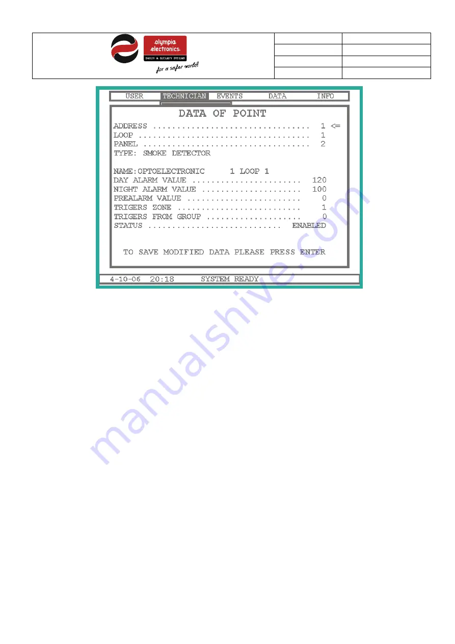
Figure 5-9
Point configuration.
Depending on the type of the installed point the screen shows the according settings.
We can change the address or the loop by using the arrow keys
«LEFT»
and
«RIGHT»
.
To set the setting press the
«ENTER»
key.
The screen shows the following fields :
TYPE
: Describes the type of point. If no point is installed then this field has “------“ markings.
NAME
: The name of the point with a total of 32 characters.
DAY TIME ALARM LIMIT
: The alarm value of the point during the day time. If this limit is exceeded during the day
time an alarm is issued.
NIGHT TIME ALARM LIMIT
: The alarm value of the point during the night time. If this limit is exceeded during the
night time an alarm is issued.
PRE-ALARM VALUE
: The pre-alarm value of the device. If this value is exceeded then the device gives a pre-alarm.
ACTIVATES THE ZONE
: When the sensors are activated it also activates the stated zone.
ACTIVATES THE GROUP
: When the sensors are activated it also activates the stated group.
STATUS
: The status of the point (if it is activated or deactivated).
Additionally, if the point is a siren or output it also has:
SILENCE CAPABILITY
: If
YES
is selected then the siren or output with silence with a command
«SILENCE SIRENS» .
If
we select
NO
then they will not silence when the SILENCE SIREN key is pressed.
DELAY BEFORE ACTIVATION
: Delay before activation in seconds (1-240).
ACTIVATION METHOD
: Change the method of activation (0 to 4).
ZONE (1-96) FUNCTION (97-150)
: The siren or output are activated by a zone or a function or by a general alarm (if
0 is selected).
To change a setting of a point, move the arrow to show the setting that we want to change and then press
«ENTER»
.
If you require to change the type of the point move to the TYPE setting and press
«ENTER» .
The screen will show the
following:


