background image

Outdoor Living Today                www.outdoorlivingtoday.com             [email protected]

Page 28

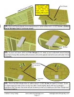
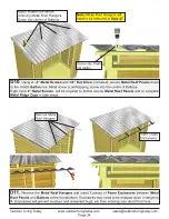
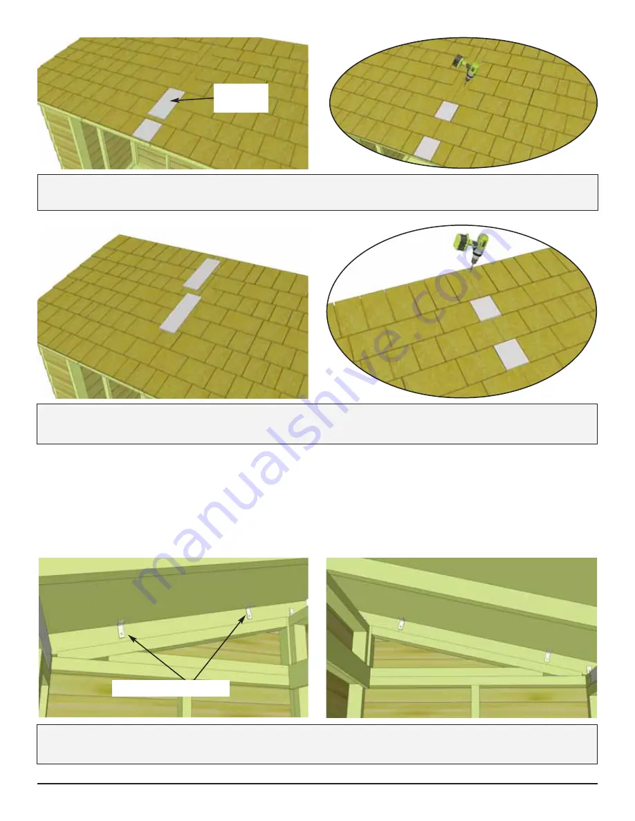
D8. 

Slide 3rd and 4th 

Filler Shingles

 up and underneath appropriate shingle rows and follow 

Steps 

D5 - D6 

to align and attach. On last filler, screws will get covered by Roof Ridge Board (4 1/2” wide).

D7. 

Slide 2nd 

Filler Shingle

 up and underneath fourth shingle row. Follow 

Steps D5 - D6

 to align 

and attach.

2nd Filler 
Shingle.

4th Shingle Row

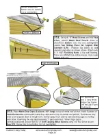
D9.

 Secure roof panels to walls at both ends by positioning 

2 - 90° Metal Brackets

 on plywood and  

outside rafters and securing with 

2 - 1 1/4” Screws

 per bracket. Complete both sides. 

90° Metal Brackets 

Summary of Contents for 84-D-BASE-BEV

Page 1: ...ufacturing and workmanship Costs incurred for customer installations are not included Failure to use supplied parts included in this kit could result in poor product performance and may void your warr...

Page 2: ...any to ensure there are no gas or electric lines buried in the area before digging Decide on the type of foundation you will be using Concrete slab or 4 6 inches of crushed gravel with paver stones or...

Page 3: ...ows 3 4x4 Pressure Treated Stringers 8 long required Evenly spaced with one at each end of floor frame Saves money on materials easy to level and work with Gravel with Patio Paver Stones Excavate at l...

Page 4: ...w x 56 d 1 Left 1 Right 4 5 Wide x 16 to 18 long Filler Shingles 2 x 4 x 51 5 8 Roof Ridge Boards D1 D11 D Roof Section METAL 6 x 3 x 50 Roof Battens 4 x 1 x 21 1 2 Batten Spacers 2 x x 51 Rafter Fac...

Page 5: ...dle Drop Latch 90 Metal Brackets x 4 pcs Square Drive Bit 2 1 2 1 1 4 3 4 2 1 1 2 Finishing Nail x 140 x 90 x 32 x 30 x 250 x 1 Black Headed Black Headed 3 x 10 x 14 1 4 x 2 1 4 Nut Driver Metal Roof...

Page 6: ...ssembly instructions will diverge to note important differences between sheds When following assembly steps keep your desired roof slope in mind relative to the doors Tools Required Not Provided Safet...

Page 7: ...ar Roof Sheds 1 2 3 4 5 6 7 Sill Gasket Floor Joists Floor Runner Foundation 8 Floor Plywood Wall Panel Small gap between bevel siding and window trim Dab of caulking Strip of roofing paper over apex...

Page 8: ...r Joist Frame and 2 Floor Joists 1 1 2 x 3 1 2 x 71 7 8 as illustrated above Position Joists equally in Floor Joist Frame Use Small Floor Joist Frame as a template to determine joist position Position...

Page 9: ...equally over seam where floor frames meet 4th Runner 4th Runner 96 45 1 2 A5 With Floor Runners attached carefully flip the floor over and place on your foundation Caution you may need 2 people to as...

Page 10: ...rectly positioned attach to all floor joists with approximately 24 1 1 4 Screws Use screws every 16 Note Plywood is cut slightly smaller than floor framing Keep plywood seams tight A7 Position Plywood...

Page 11: ...en following assembly steps keep your desired roof slope in mind relative to the door SpaceSaver GardenSaver Angled Wall Extenders 2 Door Header Long with aluminum support Solid Wall Panel 4 Wall Plat...

Page 12: ...ould be flush with outside of floor framing when properly aligned Note Do not align wall siding to floor Align wall plate to outside of plywood floor When positioned correctly locate 2nd Solid Wall Pa...

Page 13: ...h both wall panel studs together as per Step B4 with 3 2 1 2 Screws B6 With Rear Wall Panel in place position other side wall panel on floor as per Step B4 B5 Rear Wall Panel Do Not Attach Walls To Fl...

Page 14: ...the 2x3 wall plate so it sits flush with floor framing and siding overhangs Note Narrow Wall Panel is only 73 high B9 When correctly positioned secure Narrow Wall Stud to Side Wall Stud with 3 2 1 2...

Page 15: ...out and with support strip to the inside of shed Attach using 2 2 1 2 Screws per end as shown above Hint Have 2 helpers push Side Walls together to close any gaps between Headers Complete both sides A...

Page 16: ...4 Locate both Angled Wall Extenders L R Place first wall extender on side wall panel frame Note Bottom siding of wall extender will overhang and cover siding of side wall Side Wall Panel B15 Align wal...

Page 17: ...tdoorlivingtoday com Page 17 GARDENSAVER SPACESAVER B16 With Angled Wall Extender and Side Wall aligned correctly secure together from the inside with 4 2 1 2 Screws B17 Complete opposite Angled Wall...

Page 18: ...with 5 2 1 2 Screws B18 Locate one Wall Extender and place on rear wall panel with siding of extender overlapping that of the rear wall B18 Locate one Wall Extender and place on Door Header with exten...

Page 19: ...ch Cleats with 8 1 1 4 Screws B20 Position and secure 2nd Wall Extender Panel as per Steps B18 B19 Additionally attach to first Extender with 2 2 1 2 Screws B21 Attach Horizontal Wall Cleats 1 3 4 x 3...

Page 20: ...is 64 wide Prior to securing make sure wall panels are aligned correctly on the floor Wall siding should overhang floor while 2x3 wall plates should sit flush with floor Confirm Doorway opening is 64...

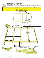
Page 21: ...void splitting wood The hole depth should be equal to 3 4 the length of screw Confirm angles on rafter ends are aligned C Rafter Section Exploded view of all parts necessary to complete the Rafter Sec...

Page 22: ...Rear Soffits and 2 Front Soffits Center Rafter has 3 4 cleats attached on both sides making the width 3 Lay out on level ground and assemble as shown in Illustrations A through C below Attach Soffit B...

Page 23: ...itioned equally from side to side C4 When Rafter Section is positioned correctly both Front and Rear Soffits will sit approximately 1 8 away from wall siding This can vary slightly C2 Carefully flip c...

Page 24: ...secure 2 90 Metal Brackets with 1 1 4 Screws Screw into Wall Extension Framing at the rear and Wall Panel top framing at the front Complete both sides 90 Metal Brackets C6 With outside rafters properl...
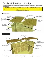
Page 25: ...Exploded view of all parts necessary to complete the Rafter and Roof Section Identify all parts prior to starting Roof Section will be installed the same way for both GardenSaver and SpaceSaver When...

Page 26: ...panel flush with plywood Attach with 4 1 1 4 Screws evenly spaced The Rafter Facia Nailing Plate provides for a greater nailing surface later when you attach side facia Rafter Facia Nailing Plate O u...

Page 27: ...Filler Shingle 5 1 2 wide up and underneath second shingle row Push or bang filler carefully with a hammer until evenly spaced and butt is even with other 1st row of shingles Tip Butt thicker 1st Shin...

Page 28: ...ch On last filler screws will get covered by Roof Ridge Board 4 1 2 wide D7 Slide 2nd Filler Shingle up and underneath fourth shingle row Follow Steps D5 D6 to align and attach 2nd Filler Shingle 4th...

Page 29: ...rafter while securing Locate Top Siding Piece for Angled Wall Extender L R Position top siding on wall extender and align as shown above Attach with 3 1 1 2 Finishing Nails to top wall framing There a...

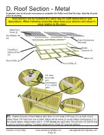
Page 30: ...the same way for both GardenSaver and SpaceSaver When following assembly steps keep your desired roof slope in mind relative to the door D1 Position first row of Roof Battens 3 4 thick x 3 1 2 wide x...

Page 31: ...f Battens 2 pcs x 3 4 thick x 3 1 2 wide x 50 long and attach flush with previously attached Batten Spacers via the same method as Step D2 Attach a second row of Batten Spacers flush with the top edge...

Page 32: ...oof Hangers 3pcs and Metal Roof Panels 3pcs 39 wide x 58 1 2 long Identical To temporarily help hold the Metal Roof Panel in place hook a Metal Roof Hanger onto the lower Batten approximately where th...

Page 33: ...ired overall width Overall width past the end of Battens can vary from 1 3 depending on your personal preference Metal roof Panels should overlap each other D9 Once Metal Roof is spaced correctly from...

Page 34: ...to complete Metal Ridge Caps in later steps Attach middle row before removing Metal Roof Hangers Screw into center of Battens Screw into Peak not valley Note Metal Roof Hangers will need to be remove...

Page 35: ...ens Secure lower front Batten row be careful not to overtighten 1 4 Nut Driver and 2 long Metal Ridge Cap Screw Drill through Foam Enclosures Foam Enclosures D13 Place Metal Drip Caps 2 pieces 60 long...

Page 36: ...ng outside rafter by 2 In the front plywood will be recessed 1 8 back from rafter end 48 wide 32 deep 2 overhang Sits on outside of middle rafter 1 D Roof Section PLYWOOD Exploded view of all parts ne...

Page 37: ...roximately 10 apart Be sure to attach screws into center of rafters as shown above D3 Locate Short Plywood Roof Panel 48 wide x 21 3 4 long and position on rafters tight against large roof panel Posit...

Page 38: ...ttach side facia Locate Top Siding Piece for Angled Wall Extender L R Position top siding on wall extender and align as shown above Attach with 3 1 1 2 Finishing Nails to top wall framing There are le...

Page 39: ...Trim 2 Side Rear Corner Trim 2 Interior Door Flange Upper Door Stop Upper Side Interior Door Stops 4 E Miscellaneous Section Misc Section will be installed the same way for both GardenSaver and SpaceS...

Page 40: ...in center Skirting meets flush in center E4 Use 6 1 1 2 Finishing Nails on front skirting piece where doors will be installed This ads extra support to a high traffic area Outdoor Living Today www ou...

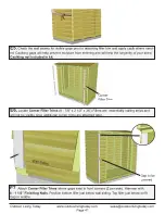
Page 41: ...rim E5 Check the wall seams for visible gaps prior to attaching filler trim and apply caulk where need ed Caulking gaps will help prevent moisture from entering and will help the longevity of your she...

Page 42: ...as per Step E7 There is an additional 10 long Rear Center Corner Filler Trim that you will need to center and attach as well using 2 1 1 2 Nails E9 Locate Vertical Door Trim 2 1 2 x 3 1 2 x 79 Positi...

Page 43: ...underneath soffit to determine vertical height Attach with 8 1 1 2 Finishing Nails per piece Position and attach Side Front Corner Trim 2 1 2 wide using 8 1 1 2 Finishing Nails aligning at bottom with...

Page 44: ...2 1 2 x 88 1 4 and Front Middle Trim 1 2 x 2 1 2 x 8 5 8 Position as shown above and attach with 1 1 2 Finishing Nails Centered on seam of Extender Walls Tight against top of Vertical Door Trim Attac...

Page 45: ...inges to narrow trim with 2 Black Screws E17 Now secure the Double Doors Starting with Right Side Door position so there is a 1 2 gap on bottom and approximately 3 8 on the side Use a spare piece of s...

Page 46: ...1 2 Nails securing them into the nailing plate closer to the top of the side facia board Attach next piece of Front Facia Note With Front Facia correctly aligned at corners a small gap may occur at ce...

Page 47: ...e E24 Attach Upper Interior Door Trim 2 1 2 x 1 2 x 28 7 8 positioning 1st trim against door jamb and underneath door header flush to edges on inside as shown to the right Attach with 4 1 1 2 Finishin...

Page 48: ...door trim E26 Attach Upper Door Stop dado cut 1 1 2 x 2 1 2 x 6 underneath door header with 2 2 1 2 Screws Stop is pre drilled on angle Evenly space between trim Door Trim Door Stop has dado cut E27 A...

Page 49: ...nge E29 To secure doors you will need to install the Interior Cane Bolt to the Vertical Door Flange First slide bolt through the upper and lower brackets Usually the upper bracket is positioned betwee...

Page 50: ...t to position Drop Latch correctly Important Drill pilot holes with 1 8 drill bit prior to securing with screws to prevent wood splitting On 3 4 screw drill shallow pilot hole only E30 Once the Cane B...

Page 51: ...al color we suggest that you treat the wood with a good oil base wood stain You may also wish to paint your new shed rather than stain it In both cases we recommend that you consult with a paint and s...

Reviews: