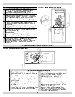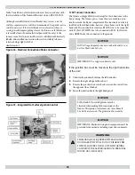
120V Furnace Connection
Th
e furnace is shipped fully wired except for the connections to the
house wiring. Th
e furnace power connections are made in a junc-
tion box inside the blower compartment. Th
e junction box is factory
installed on the left hand side; however, it may be moved to the right
hand side. Th
e junction box contains a BLACK wire to be connected
with L1 (hot), a WHITE wire to be connected with L2, the Neutral,
and a GREEN wire to be connected to the ground.
NOTICE
NOTE: Use good quality wire nuts such as Marrette® con-
nectors, Ideal® wire nuts, etc.
NOTICE
IMPORTANT: Use copper conductors only
If the junction box must be moved to the right hand side
of the unit:
1.
Unfasten the junction box from the left hand side.
2.
Remove the right side panel knock-out.
3.
Remove the junction box cover hook screw and re-install it on
the opposite side of the box.
4.
Fasten the junction box to the right hand panel.
NOTICE
L1 (hot) and L2 (neutral) polarity must be
observed when making fi eld connections to the
furnace. Th
e ignition control may not sense fl ame if
L1 and L2 are reversed. Th
e ground is also essential.
NOTICE
IMPORTANT: Electrical wiring and components must be
protected from moisture including water and condensate.
!
WARNING
THIS FURNACE IS EQUIPPED WITH A BLOWER
DOOR SAFETY SWITCH. DO NOT DISABLE THIS
SWITCH. FAILURE TO FOLLOW THIS WARNING
CAN RESULT IN ELECTRICAL SHOCK, PERSONAL
INJURY, OR LOSS OF LIFE.
In the United States, all electrical work must be in accordance with
the latest edition of the National Electrical Code, ANSI / NFPA 70.
Although a suitably located circuit breaker may serve as a service
switch, a separate service switch is recommended. A separate service
switch is necessary if the circuit breaker is in a location where ac-
cessing it would require getting close to the furnace, or if the furnace
is located between the main electrical panel and the entry to the
furnace room. Th
e furnace switch (service switch) should be clearly
labeled, and installed in a location where it is not likely to be mis-
taken as being a light switch or
similar control.
19 - ELECTRICAL SPECIFICATIONS
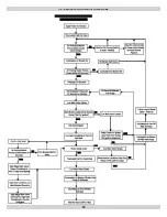
Figure 34 - Electrical Connections/Molex Connector
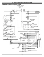
Figure 35 - Integrated Hot Surface Ignition Control
40


