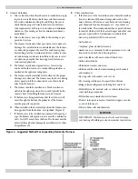
In Canada
In addition to the general guidelines, both non-direct and direct vent
exhaust shall not terminate:
• Directly above a paved sidewalk or paved driveway which is
located between two single-family dwellings and serves both
dwellings;
• Less than 7 feet above a paved sidewalk or paved driveway
located on public property;
• Within 6 feet of a mechanical air supply inlet to any building;
• Above a meter/regulator assembly within 3 feet horizontally of
the centerline of the regulator;
• Within 6 feet of any service regulator vent outlet;
• Less than 12” above grade level or anticipated snow level;
• Within 12” of any door, window, or non-mechanical air sup-
ply inlet to any building;
• Within 12” of the combustion air inlet of any other appliance;
Note: Canadian installations of 120,000 BTU/h requires 3 ft .
(900 mm)
• Underneath a veranda, porch or deck, unless (a) the veranda,
porch or deck is fully open on a minimum of two sides be-
neath the fl oor, and (b) the distance between the top of the
vent termination and the underside of the veranda, porch or
deck is greater than 12”.
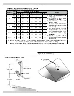
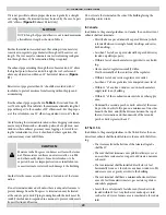
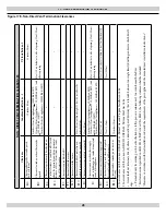
• Refer to Figures
17A and 17B
for terminal clearances.
In The U.S.A.
In addition to the general guidelines, in the United States, both non-
direct and direct vent exhaust shall be installed in accordance with
the following:
• Th
e clearance from the bottom of the terminal to grade shall
be 12”.
• Th
e vent shall not terminate over public walkways or over an
area where condensate or vapor could create a nuisance or
hazard.
• Th
e vent terminal shall be installed at least 1 foot from any
opening through which fl ue gases could enter a building.
• Th
e vent terminal shall have a minimum horizontal clearance
of 4 feet from electric meters, gas meters, regulators and relief
equipment.
• Locate the vent terminal 3 feet horizontally from the vent of
any side wall vented fuel gas appliance or electric clothes dryer,
except in the case where two or more of these furnaces are
multi-vented.
(See “Multiple Venting”)
• Refer to
Figures 17A and 17B
for terminal clearances.
FURNACE CONNECTION
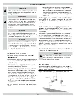
NOTICE
IMPORTANT: Clean and de-burr all pipe cuts. Th
e shav-
ings must not be allowed to block the exhaust, combustion
air inlet or condensate drain lines.
NOTICE
IMPORTANT: If the pipe and fi ttings are to be other than
PVC, use the proper cleaner, primer and cement for the
dissimilar materials.
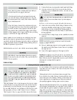
!
WARNING
Th
ere must not be any openings between the blower divi-
sion panel and the combustion compartment. Th
e blower
compartment is under greater suction then the combus-
tion compartment and can pull combustion air from the
burners and cause incomplete combustion and erratic
furnace operation.
!
WARNING
Th
e vent must be clamped to the furnace panel using
the gasket and clamp provided. Th
e intake must use the
threaded PVC connector with the gasket and lock nut.
Routing Options -
Th
e furnace can be installed in any of four
positions.
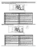
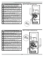
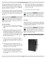
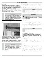
Figures 18-25
on the following pages show the four po-
sitions. Th
e installer must consider the following services: gas pipe,
electrical power, drain trap, intake and exhaust vents. Also consider
the air conditioning connections and drain, access to fi lter(s) and
access to furnace and a/c for repair. Drains and traps of furnaces
installed in spaces subjected to freezing temperature must also be
protected against freezing.
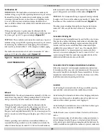
Th
e vent must be clamped to the exterior panel(s) with the clamp
provided. Place the gasket between the clamp and the side panel.
Tighten clamp and fasten in place using the three screws provided.
Th
e clamp should secure the vent pipe to prevent internal damage if
the vent pipe is tampered with.
Th
e combustion air inlet fi tting is a 2” PVC Socket to Pipe Th
read
adapter. Chose the intake location and open the appropriate knock
out. Install the adapter to the exterior panel using the gasket (on the
outside of the panel and the locknut on the inside of the panel.
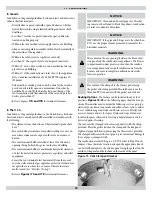
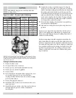
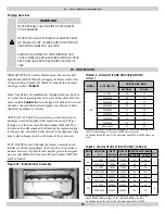
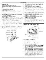
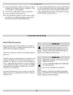
Figure 15 -Vent Clamp and Gasket
13 - TERMINATIONS
24

