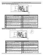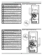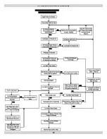
Conversion Steps
To convert from sea level to high altitude, from
natural gas to LP gas, or from LP gas to natural gas, follow these
steps:
1.
Turn off gas supply to the furnace.
2.
Shut off electrical power to the furnace.
3.
Remove the front door to expose the gas train and burner as-
sembly.
4.
Unfasten the ground joint union between the gas valve and gas
supply piping if applicable.
5.
Unplug the wires connected to the gas valve.
6.
Unfasten the burner manifold pipe from the burner assembly. It
is held in place by 2 screws on either end of the manifold pipe.
7.
Remove the existing orifi ces with a
7/16” socket, box or open end wrench. Install the replace-
ment orifi ces. Th
e orifi ce spuds are brass, and do not normally
require pipe dope. A light grease may be used to lubricate
the threads. Th
e orifi ce spuds have tapered threads.
DO NOT
OVER-TIGHTEN!!
18 - CONVERSIONS
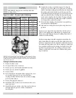
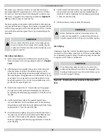
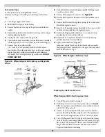
Figure 30 - White-Rodgers 36G54 Springs and Regulator
Screws
8.
Re-install the burner manifold pipe assembly following steps 4,
5, and 6 in reverse order.
9.
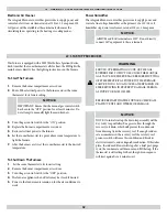
Remove both regulator cover screws. See
Figure 30
.
10.
Remove both regulator adjustment screws (beneath the cover
screws).
11.
Remove both Natural Gas regulator springs (color-coded silver/
plain) from regulator sleeves.
12.
Insert the L.P. regulator springs (provided in the conversion kit
and color-coded white) into the regulator sleeves.
13.
Replace the High regulator adjustment screw and adjust ap-
proximately 12 turns in, from fully out.
14.
Replace the Low regulator adjustment screw and adjust ap-
proximately 8 turns in, from fully out.
15.
Apply a liberal amount of pipe joint
compound or pipe thread tape to the threads and reassemble
the piping previously removed. Note: the pipe joint compound
must be resistant to L.P. gas.
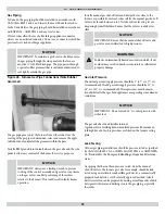
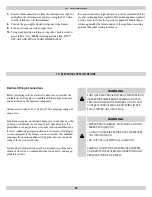
Figure 31 - White Rodgers 36G54 Gas Valve
Checking The INLET Gas Pressure
White-Rodgers 36G54 Two Stage Gas Valve.
1.
Turn off the gas and electrical supply.
2.
Back inlet pressure test screw (inlet pressure boss, see
F
igure
31
) out one turn (counterclockwise, not more than one turn)
with a 3/32” Allen wrench.
3.
Attach a hose and calibrated U-tube manometer to the inlet
pressure boss. Hose should overlap boss 3/8”. Th
e manometer
must have a scale range of at least 0” to 15” of water column.
4.
Turn ON the gas and electrical supply and operate the furnace
and all other gas consuming appliances on the same gas supply
line. Using a soap and water solution, check for leaks around
the gas valve/manifold connection and the burner orifi ces.
Repair any leaks before continuing.
37


