683311W
8-6
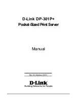
8.1.5 ADJUSTING THE PRINT BAR
MACHINE CONDITION:
The print head must be in a coaxial position with respect to the axis of the screw used for this
adjustment.
OBJECTIVE ADJUSTMENT:
A distance of 0.4/0.5 mm must be measured between the frame's lower shield (1) and the head of
screw (2).
PROCEDURE:
While holding the print head carriage on the axis, adjust screw (2) until obtaining the required distance.
Repeate this procedure on the other screw located on the opposite side of the frame.
Fig. 8-5
2
1
0.4/0.5
PRINT HEAD
Summary of Contents for PR2 plus
Page 1: ...PR2 PRINTER SERVICE MANUAL Code Y683311W 01...
Page 4: ......
Page 12: ...683311W 1 4 Fig 1 2 PR 2 with Flat Cover Fig 1 1 PR 2 Printer with Rounded Cover...
Page 24: ......
Page 34: ......
Page 52: ......
Page 130: ......
Page 136: ......
Page 154: ......
Page 178: ......