background image


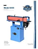
Sander


Model 6303


Owner’s Manual  

For Models Manufactured Since 07/2017 


Oliver Machinery 

1-800-559-5065 

921 Thomas Ave SW,  

Renton, WA 98057


[email protected] 


Stock Number: 6903.001 

Manual Version: 2.0.0


Summary of Contents for 6303

Page 1: ...nder Model 6303 Owner s Manual For Models Manufactured Since 07 2017 Oliver Machinery 1 800 559 5065 921 Thomas Ave SW Renton WA 98057 info olivermachinery net Stock Number 6903 001 Manual Version 2 0...

Page 2: ...CHINERY RESERVES THE RIGHT TO EFFECT AT ANY TIME WITHOUT PRIOR NOTICE THOSE ALTERATIONS TO PARTS FITTINGS AND ACCESSORY EQUIPMENT WHICH THEY MAY DEEM NECESSARY FOR ANY REASON WHATSOEVER SAVE THIS MANU...

Page 3: ...ust Chute Installation 22 Stop Bracket Installation 22 Set Up Contour Sanding Table 23 Dust Collection 24 Test Run 25 Operation 26 Preparation before Sanding 26 Material Selection and Inspection 26 Su...

Page 4: ...cifications drawings and photographs in this manual should match the machine delivered If you find any differences or anything that seems confusing in this manual please check our website for an updat...

Page 5: ...uct Dimensions Width x Depth x Height Fully Assembled 48 W x 23 D x 48 H Footprint 21 1 2 W x 16 1 2 D Fully Assembled Weight 257 lbs Shipment Info Packaging Cardboard Box and Pallet Content Sander wi...

Page 6: ...n Steel with Graphite Coating Platen Dimensions 32 1 2 x 7 Table Material Precision Ground Cast Iron Main Table Dimensions 29 3 4 W x 10 D Main Table Height from Floor 37 3 4 40 3 4 Miter Slot Type T...

Page 7: ...6303 Sander OLIVERMACHINERY NET 7 Page Identification...

Page 8: ...suitable ground Follow the grounding procedure indicated in the electrical code of your area 3 DISCONNECT the machine from power before performing any service maintenance adjustments or when changing...

Page 9: ...Do not operate this machine while under the influence of drugs alcohol or when not feeling well 11 NEVER STAND ON MACHINE This prevents injuries from tipping related accidents and accidental contacts...

Page 10: ...aintain control of the workpiece Hold the workpiece firmly with both hands and apply light pressure against the sanding belt Use the sander table backstop miter gauge or fence to support the workpiece...

Page 11: ...ed circuit is properly sized for safe operation If a circuit is available but not meeting the minimum circuit size requirement listed above a new circuit must be installed for this machine Grounding W...

Page 12: ...wer source select a durable cord type with high temperature rating 90C or above Use the minimum amount of extension cord as needed Minimum cord size AWG required based on amperage draw and length of t...

Page 13: ...machine the operator and related items Electricals Make sure a properly sized circuit and electrical outlet are available near the machine Please refer to section Electricals on page 11 for details re...

Page 14: ...y default On the day of delivery please be sure help is available to move the machine to its final location WARNING 6303 Sander has a gross weight of 273 lbs and a net weight of 257 lbs Safe moving te...

Page 15: ...iption Quantity 1 Rubber Feet 4 2 Round Head Screws 5 16 18 3 4 4 3 Washers 5 16 4 4 Nuts 5 16 4 Package 2 Mounting hardware Item Description Quantity 5 Fender washers 5 16 4 6 Washers 5 16 18 7 Lock...

Page 16: ...o check if a component is included or installed NOTICE This machine comes with various standard sized non proprietary parts If any of these parts are missing we be happy to deliver them to you To have...

Page 17: ...Installation 1 Gather all hardware in Package 1 2 Insert the round head screw and washer into the rubber feet 3 Mount the feet at the bottom of the side panel Thread a nut into the screw 4 Hold the b...

Page 18: ...eet already mounted 2 All mounting hardware in Package 2 Item Description Quantity 5 Fender washers 5 16 4 6 Washers 5 16 18 7 Lock washers 5 16 10 8 Hex nuts 5 16 8 9 Hex nuts 5 16 10 3 The shelf and...

Page 19: ...the base of the sander assembly it s recommended to install the panels upside down on a flat surface Tighten the bolts to hold the panels together but do not fully tighten them yet 5 Place the cabine...

Page 20: ...ting hardware package prepare two sets of flat washers 6 lock washers 7 and 5 16 hex bolts 9 Insert the lock washer into the bolt and then the flat washer 5 Secure the sander assembly on the cabinet T...

Page 21: ...e fence and the sanding belt are loosely packed inside 4 Install the belt tension lever handle that is located on the top of the platen assembly Use a mallet to gently tap the handle into the lever 5...

Page 22: ...lation 1 The stop bracket provides support to the workpiece and prevents the workpiece from getting dragged into the dust chute It should be installed while the machine is in use 2 The stop bracket mo...

Page 23: ...the dust chute lock knob Swing the dust chute to the back of the machine to allow room to install the table 4 Install the lock knob then insert the post into the mounting bracket Align the flat surfac...

Page 24: ...to a dust collection system The minimum CFM requirement for this sander is 650 CFM at the dust port which means the dust collection system should have a rating greater than 650 CFM as air friction an...

Page 25: ...er stationary parts 5 Connect the machine to power 6 Turn on the machine The sanding belt should oscillate and track within the platen If the sanding belt is not tracking properly TURN OFF MACHINE IMM...

Page 26: ...staples rock chips and other objects embedded on the wood surface can damage the sanding belt Clean the workpiece with a stiff brush as needed The workpiece should have at least one flat surface so i...

Page 27: ...the main table 2 Adjust the table height Make sure the table is positioned at least 1 16 above the bottom edge of the sanding belt so it is level with the sanding belt 3 Tighten the table lock knobs...

Page 28: ...ter angle against the sanding belt before use 5 Before starting the sander clear the table and turn on the dust collection system 6 Turn on the sander 7 Hold the workpiece firmly on the table and use...

Page 29: ...ith this sander provides an additional surface to support the workpiece 5 To install the fence insert the guiding blocks into the miter slot and align them with the fence s slots 6 Secure the fence wi...

Page 30: ...the concaved abrasive surface for contour sanding 6 Remove the contour sanding table and close the dust chute when the operation completes WARNING Avoid sanding edges with curvature closely matching...

Page 31: ...our website OLIVERMACHINERY NET To order by phone please call us at 1 800 559 5065 We are available Monday through Friday 9AM 5PM Pacific Time You can also email us at PARTS OLIVERMACHINERY NET to pu...

Page 32: ...er switch cord and plugs for signs of failure Every day before any operation begins Inspect the sanding belt for signs of failure Every day before any operation begins Clean sanding belt with belt cle...

Page 33: ...oning lever to the Loose position 6 Gently slide the sanding belt off the drums 7 The sanding belt rotates counter clockwise when the sander runs Make sure the arrows on the back of the sanding belt a...

Page 34: ...wer edges of the drums as it oscillates If adjustment is needed 1 Turn off the sander 2 Loosen the lock nut 3 Rotate the belt tracking adjustment bolt CLOCKWISE to raise the belt on the drum and COUNT...

Page 35: ...sion cord too light or too long Use a shorter heavier cord that meets this machine s electrical requirements Machine stalls or does not come up to speed Extension cord too light or too long Use a shor...

Page 36: ...r feed pressure Sanding belt clogs easily Sanding softwood or wood with high resin content Clean replace belt more frequently Sanding wet stock Dry stock before operation Sanding non wood materials So...

Page 37: ...6303 Sander OLIVERMACHINERY NET 37 Page Wiring Diagrams...

Page 38: ...38 Page Oliver Machinery 6303 Sander Parts List Table and Base...

Page 39: ...6303 Sander OLIVERMACHINERY NET 39 Page Stand...

Page 40: ...40 Page Oliver Machinery 6303 Sander Motor and Sander Assembly...

Page 41: ...6303 Sander OLIVERMACHINERY NET 41 Page Idler Drum...

Page 42: ...20101011A Table 1 17A S0020510 Cap Screw 5 16 18UNC 5 8 4 18 20101065 Special Screw 2 19 S0111000M Nut M10 2 19A S0230308 Spring Washer 3 8 2 20 20101013 Guide Block 2 21 20101014 Fence 1 22 20101015...

Page 43: ...Flat Head Screw 3 16 3 4 1 59 10102022 Scale Pointer 1 60 S0040300 Flat Head Screw 3 16 24UNC 3 8 1 61 M0000000 Motor 1 5HP 1Ph 115 230V 1 62 S0020520 Hex Head Screw 5 16 18UNC 1 1 4 5 63 S0210500C Fl...

Page 44: ...0510M Phillips Head Screw M5 P0 8 10 2 118 20101048A Graphite Platen Pad 1 119 20104054J Left or Right Stand Side Panel 2 120 20104053 Rear Stand Panel 1 121 20104053J Front Stand Panel 1 122 20104052...

Page 45: ...Socket Set Screw 6 6 2 185 21700051G Idler Drum Shaft 1 186 S0400540 Key 5 5 40 1 188 21700009 Worm 1 191 S0400425 Key 4 4 25 1 193 W1017W 2 Cord Strain Relief 2 194 21700032 Connecting Plate 1 203 11...

Page 46: ...46 Page Oliver Machinery 6303 Sander Maintenance Record Date Task Operator...

Page 47: ...6303 Sander OLIVERMACHINERY NET 47 Page Notes...

Page 48: ...s due to direct or indirect misuse abuse negligence accidents unauthorized repairs alternation outside our facilities lack of maintenance acts of nature or items that would normally be consumed or req...

Page 49: ......

Page 50: ...always adding new Industrial Woodworking products to the line For complete up to date product information visit us online at WWW OLIVERMACHINERY NET or call toll free 1 800 559 5065 SAVE THIS MANUAL F...

Reviews: