background image

12

1

2

3

4

Italiano

English

Français

ASSEMBLAGGIO

ASSEMBLY

ASSEMBLAGE

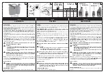
La macchina si presenta come nelle Fig. 1-2.

Montaggio dei tubi/impugnatura

  ATTENZIONE – Quando si montano i tubi e 

l’ugello, il motore deve essere spento e 
l’interruttore deve essere sulla posizione STOP.

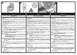
1. Montaggio impugnatura: vedi Fig. 3-4.
2. Collegare il tubo flessibile (A, Fig.1) al tubo in uscita 

dalla ventola (B) mediante la fascetta stringitubo (C1). 
Collegare il tubo flessibile (A, Fig.1) al tubo (N) 
mediante la fascetta stringitubo (C2). Nell’eseguire il 
montaggio, prestare attenzione alle due tacche poste 
sul tubo flessibile (G, Fig. 5) e sui tubi (F) che devono 
accoppiarsi tra di loro. Prima di serrare la vite della 
fascetta stringitubo (C1, Fig. 6), inserire nell’apposito 
alloggiamento il tubo del cavo acceleratore (H).

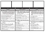
3. Innestare il tubo soffiatore (D, Fig.2) e l’ugello (E1) o 

(E2) imboccando i due perni (L, Fig. 7) sulle due 
scanalature (M). Ruotare nella direzione della freccia 
(2) fino al bloccaggio. I tubi montati risulteranno 
come in Fig. 8.

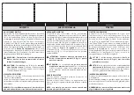
4. Prestare attenzione al montaggio dell’ugello 

(E1, Fig. 2), verificando che a montaggio effettuato 
l’uscita del tubo sia rivolta verso l’alto.

5.  OPZIONALE – Per rendere più direzionabile ed 

efficace il getto soffiante è possibile montare il tubo 
con sezione d’uscita a becco d’anatra (L, Fig.2) al 
posto dell’ugello. Il kit cod. 56552002 è acquistabile 
separatamente. Per il montaggio seguire le istruzioni 
del punto 3. 

The assembled machine appears as in Figures 1-2.

Assembling the tubes/handgrip

  WARNING – When fitting the tube and nozzle, 

the engine must be off and the switch in the 
STOP position.

1. Handgrip assembling: Fig. 3-4.
2. Connect the flexible tube (A, Fig.1) to the fan outlet 

(B) and secure with the clip (C1). Connect the flexible 
tube (A, Fig.1) to the tube (N) and secure with the clip 
(C2). When making the connection, make certain that 
the notch (G, Fig. 5) on the flexible tube is aligned 
with the button (F) on the tubes so that the two parts 
couple properly together. Before tightening the screw 
to secure the clip (C1, Fig. 6), locate the throttle cable 
sheath (H) in the guide loop.

2. Couple the blower tube (D, Fig.2) and the nozzle (E1) 

or (E2) by locating the two pins (L, Fig. 7) in the 
grooves (M) and then twisting in the direction of the 
arrow (2) until locked. The assembled tubes should 
appear as in Fig. 8.

4. When fitting the nozzle (E1, Fig.2), make certain that 

the curved tip is directed upwards.

5.  OPTIONAL – To obtain a more directional and 

effective jet of air when blowinH, the duckbill style 
outlet can be fitted to the tube (L, Fig.2) in place of 
the nozzle. The kit, p/n 56552002, can be purchased 
separately. To assemble, follow the instructions of 
point 3. 

La machine se présente comme indiqué Fig. 1-2.

Montage des tubes/poignée

  ATTENTION – Quand on monte les tubes et la 

buse, le moteur doit être éteint et l'interrupteur 
en position STOP.

1. Montage poignée: Fig. 3-4.
2. Relier le tuyau flexible (A, Fig.1) au tube en sortie de 

ventilateur (B) à l'aide du collier serre-tube (C1). Relier 
le tuyau flexible (A, Fig.1) au tube (N) à l'aide du collier 
serre-tube (C2). Lors du montage, faire attention aux 
deux repères placés sur le tuyau flexible (G, Fig. 5) et 
sur les tubes (F) qui doivent être accouplés. Avant de 
serrer la vis du collier serre-tube (C1, Fig. 6), insérer 
dans le logement le tube du câble accélérateur (H).

3. Enclencher le tube du souffleur (D, Fig. 2) et le gicleur 

(E1) ou (E2) en engageant les deux pivots (L, Fig. 7) 
sur les deux gorges (M). Tourner dans le sens de la 
flèche (2) jusqu'à l'encliquetage. Les tubes seront 
alors montés comme indiqué sur la Fig. 8.

4. Faire attention au montage du gicleur (E1, Fig. 2), en 

vérifiant qu'une fois le montage effectué la sortie du 
tube soit tournée vers le haut.

5.  OPTION – Pour mieux contrôler la direction et 

l'efficacité du jet soufflant monter le tube à section 
d'ouverture en bec de canard (L, Fig.2) à la place de 
la buse. Le kit cod. 56552002 est vendu séparément. 
Pour le montage suivre les instructions du point 3. 

Summary of Contents for BV 162

Page 1: ...3 cm3 I D F GB E NL OWNER S MANUAL MANUALE USO E MANUTENZIONE BETRIEBS UND WARTUNGSANLEITUNG MANUEL D UTILISATION ET D ENTRETIEN MANUAL DE USO Y MANTENIMIENTO GEBRUIKSAANWIJZING Pubbl 56520148A rev 3...

Page 2: ...Anpassung der vorliegenden Bedienungsanleitung vorzunehmen E INTRODUCCION TRADUCCI N DE LAS INSTRUCCIONES ORIGINALES Para una correcta utilizaci n del sopladore y para evitar accidentes no empiece a t...

Page 3: ...4 MAINTENANCE CHART______________ 46 TROUBLE SHOOTING CHART _________ 49 WARRANTY CERTIFICATE ____________ 52 INTRODUCCION ___________________ 2 EXPLICACION SIMBOLOS Y ADVERTENCI S DE SEGURIDAD ______...

Page 4: ...or der Inbetriebnahme lesen 2 Immer Helm Schutzbrille und Ger uschschutz tragen 3 Ger t BL SER 4 Garantierter akustischer Schalleistungspegel 5 Seriennummer 6 CE Zeichen 7 Baujahr 8 ACHTUNG Gefahr der...

Page 5: ...arburant 12 R servoir carburant 13 Poign e de d marrage 14 Pot d chappement 15 Poign e 16 Poign e de transport 17 Harnais D BAUTEILE DES BLASER 1 D se 2 Blasrohr 3 Gashebel 4 Schutzgitter 5 Gasregler...

Page 6: ...l motore acceso 18 proibito applicare alla presa di forza del soffiatore una girante che non sia quella fornita dal costruttore Non consentito l uso di altri gruppi di applicazione perch aumentano il...

Page 7: ...ot fit the impeller to other engines or transmissions 19 When disposing of an old blower at the end of its useful life think of the environment Take your old unit to your dealer who will be able to di...

Page 8: ...e Maschine nicht mit laufendem Motor liegen lassen 18 R sten Sie den Abtrieb des Blasger ts nur mit dem Originalgebl se des Herstellers aus Die Verbindung weiterer Baugruppen ist wegen der gr eren Unf...

Page 9: ...en el medio ambiente sino entregarlo al propio vendedor quien le dar el destino correspondiente No montar el rotor en otros motores o transmisiones de potencia 20 Ceder o prestar el soplador exclusiv...

Page 10: ...ted supplier to choose an adequate equipment The clothing must be proper and not an obstacle Wear adherent protective clothing Oleo Mac protective jackets Fig 1 and dungarees Fig 2 are ideal Do not we...

Page 11: ...entos adecuados La ropa debe ser cumplir su funci n de protecci n y ser c moda Utilizar ropa adherente y protectora La chaqueta Fig 1 y el peto Fig 2 de protecci n Oleo Mac son ideales No llevar ropa...

Page 12: ...n the flexible tube is aligned with the button F on the tubes so that the two parts couple properly together Before tightening the screw to secure the clip C1 Fig 6 locate the throttle cable sheath H...

Page 13: ...F Fig 5 se encastre en el alojamiento practicado en el tubo flexible G Antes de apretar el tornillo de la abrazadera C1 Fig 6 pase el tubo del cable del acelerador H por el orificio de gu a 3 Una el t...

Page 14: ...d position the buckles Fig 9 so that the machine is ideally balanced and at a suitable height Handgrip The handgrip can be adjusted by the operator for comfort and convenience by loosening the two scr...

Page 15: ...hebillas Fig 9 para optimizar el equilibrio y la distancia de la m quina al suelo Empu adura La empu adura puede ajustarse de acuerdo con las exigencias del usuario Para ello desenrosque los dos torni...

Page 16: ...and to keep fuel from escaping around the cap Tighten fuel cap securely after refueling Unit vibration can cause an improperly tightened fuel cap to loosen or come off and spill quantities of fuel Wi...

Page 17: ...el tap n de combustible despu s del llenado Las vibraciones pueden causar un aflojamiento del tap n y fugas de combustible Secar el combustible de las fugas de la unidad Desplazar la m quina a 3 metr...

Page 18: ...high quality engine oil JASO specification FD or ISO specification L EGD When oil specifications are NOT equivalent or unknown use 4 1 25 oil fuel mixing ratio CAUTION DO NOT USE AUTOMOTIVE OIL OR 2...

Page 19: ...as especificaciones del aceite no se conocen o NO son equivalentes utilizar una relaci n de mezcla aceite combustible del 4 1 25 PRECAUCI N NO UTILIZAR ACEITE PARA VEH CULOS O ACEITE PARA MOTORES FUER...

Page 20: ...cap clean and inspect the gasket 5 Immediately replace fuel cap and hand tighten Wipe up any fuel spillage WARNING Check for fuel leaks if any are found correct before use Contact a Servicing Dealer...

Page 21: ...que el combustible se derrame 4 Antes de volver a poner el tap n del combustible limpiar e inspeccionar la junta 5 Colocar inmediatamente el tap n y apretarlo a mano Eliminar todo eventual residuo de...

Page 22: ...o release the automatic starter The starter lever E Fig 31 should return to its original OPEN position WARNING When starting the blower with the engine already hot do not use the automatic starter E F...

Page 23: ...10 segundos y accione el acelerador B Fig 29 para desbloquear el arrancador autom tico E Fig 31 el cual debe volver a su posici n original de OPEN ATENCI N Cuando el motor ya est caliente no utilice...

Page 24: ...ng the machine down Be particularly cautious and alert when wearing ear protectors as these can restrict your ability to hear sounds indicating danger shouts signals warnings etc Be extremely careful...

Page 25: ...de protecci n que pueden limitar la capacidad de o r sonidos que indican riesgos avisos se ales advertencias etc Tener mucho cuidado al trabajar en pendiente o sobre terrenos irregulares Mantener siem...

Page 26: ...nhalation of airborne crystalline silica can cause serious or fatal respiratory disease including silicosis When encountering such materials always follow the respiratory precautions mentioned above W...

Page 27: ...granito la roca y muchos otros materiales como productos de hormig n y alba iler a La inhalaci n repetida y o intensa de s lice cristalino presente en el aire puede causar enfermedades respiratorias g...

Page 28: ...slightly spray the work area with a hose or use a mister attachment when water is available Watch out for children pets open windows or cars and blow debris safely away Use the full nozzle extension s...

Page 29: ...posici n Prestar atenci n a los ni os a los animales dom sticos a los autom viles y a las ventanas abiertas y soplar los desechos en condiciones de seguridad Utilizar el prolongador de la boquilla de...

Page 30: ...amusement parks Remove light or fluffy snow Dry off pavement and outdoor areas To remove rubbish from corners round connections and between paving stones etc WARNIG When working inside corners blow f...

Page 31: ...rucci n Limpiar anfiteatros y parques de atracciones Eliminar nieve ligera o blanda Secar aceras y reas exteriores Eliminar basura de esquinas cruces juntas entre piedras de pavimentaci n etc ATENCI N...

Page 32: ...pport before refitting the cover FUEL FILTER Periodically check the condition of the fuel filter C If excessively dirty the filter should be renewed Fig 54 ENGINE Periodically clean the cylinder fins...

Page 33: ...colocado correctamente en su soporte antes de colocar la tapa FILTRO DE COMBUSTIBLE Controle peri dicamente las condiciones del filtro de combustible C Cuando est demasiado sucio c mbielo Fig 54 MOTO...

Page 34: ...engine until warm The idle speed adjuster screw T Fig 66 is set to obtain an idle speed to 2100 100 rpm This engine is designed and manufactured in order to comply with the applicable 97 68 EC and 200...

Page 35: ...otor cumple las directivas 97 68 EC y 2002 88 EC ATENCI N No altere de ninguna manera la carburador TRANSPORTE No transportar el soplador con el motor encendido ATENCI N Para el transporte de la m qui...

Page 36: ...ively and every two years if with normal use WARNING Any maintenance operations not specifically dealt with in this manual must be carried out by an authorised service centre To ensure that your blowe...

Page 37: ...s si el uso es normal ATENCI N Todas las operaciones de mantenimiento no indicadas en este manual deben ser realizadas por un taller autorizado Para garantizar un funcionamiento correcto y constante d...

Page 38: ...cleaner B Fig 72 the cylinder fins Fig 73 and the tubes especially when the machine is used in the vacuum version Store the machine in a dry place preferably not in direct contact with the ground awa...

Page 39: ...on el suelo y lejos de fuentes de calor y del alcance de los ni os Para volver a utilizar la m quina despu s de la pausa invernal es suficiente realizar las mismas operaciones que para la puesta en ma...

Page 40: ...mbre de tours min au ralenti Minimale Drehzahl Minute N giros min m nimo Minimum toerental min min 1 2100 100 Capacit serbatoio Fuel tank capacity Capacit du r servoir Kraftstofftank Inhalt Capacidad...

Page 41: ...CNICOS NL TECHNISCHE GEGEVENS Peso weight poids gewicht kg 9 4 Massima velocit dell aria Maximum air speed Vitesse maximale de l air Max Luftgeschwindigkeit Velocidad m xima del aire Maximum luchtsnel...

Page 42: ...tainty Incertitude Unsicherheit Incertidumbre Onnauwkeurigheid dB A 1 0 Livello potenza acustica garantita Guaranteed sound power level Niveau puissance acoustique assur Garantierter akustischer schal...

Page 43: ...43 NOTE...

Page 44: ...antwoordelijkheit dat de machine 1 Genere soffiatore 1 Type blower 1 Cat gorie souffleur 1 Baurt bl ser 1 G nero soplador 1 Type bladblazer 2 Marca Tipo 2 Trademark Type 2 Marque Type 2 Marke Typ 2 Ma...

Page 45: ...spegel gemessen Nivel de potencia ac stica medido Het geluidsniveau werd gemeten Livello di potenza acustica garantita Guaranteed sound power level Niveau de puissance acoustique garanti Garantierter...

Page 46: ...Carburatore Controllare il minimo la catena non deve girare al minimo X X Candela Controllare distanza elettrodi X Sostituire X Ogni 6 mesi Sistema antivibrante Ispezionare danni e usura X MAINTENANCE...

Page 47: ...tr ler la distance des lectrodes X Remplacer X Tous les 6 mois Syst me anti vibrations V rifier dommages et niveau d usure X WARTUNGSTABELLE Die folgenden Wartungsintervalls gelten ausschlie lich bei...

Page 48: ...ncia de los electrodos X Sustituir X Cada 6 meses Sistema antivibraci n Inspeccionar da os y desgaste X ONDERHOUDSTABEL Wij wijzen u erop dat de volgende onderhoudsintervallen alleen van toepassing zi...

Page 49: ...il flusso d aria ridotto 1 Griglia di protezione ostruita 2 Girante danneggiata 3 Chiocciola e tubi ostruiti 1 Pulire griglia di protezione 2 Contattare un Centro Assistenza Autorizzato 3 Pulire TROU...

Page 50: ...r Motor startet und l uft f rdert jedoch einen geringen Luftstrom 1 Schutzgitter verstopft 2 Laufrad besch digt 3 Spirale und Rohre verstopft 1 Schutzgitter reinigen 2 Wenden Sie sich an eine autorisi...

Page 51: ...ci n 2 Llamar a un Centro de Asistencia Autorizado 3 Limpiar OPLOSSEN VAN PROBLEMEN WAARSCHUWING zet het apparaat altijd uit en koppel de bougie los voordat u de aanbevolen corrigerende maatregelen in...

Page 52: ...52 NOTE...

Page 53: ...way unsuitable lubricants and fuels have been used non original spare parts and accessories have been fitted work has been done on the machine by unauthorised personnel 5 The warranty does not cover c...

Page 54: ...nto Uso incorrecto o manipulaci n del producto Uso de lubricantes o combustibles inadecuados Uso de piezas de recambio o accesorios no originales Intervenciones efectuadas por parte de personal no aut...

Page 55: ...55 NOTE...

Page 56: ...rante tutta la sua vita GB WARNING This owner s manual must stay with the machine for all its life F ATTENTION Ce manuel doit accompagner le moteur tout au long de sa vie D ACHTUNG Bewahren Sie diese...

Reviews: