


4742-E P-68
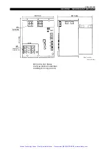
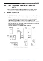
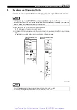
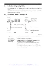
SECTION 2 DC POWER SUPPLY UNIT (MPS, MPR UNIT)
4-2.
Contents of Indication
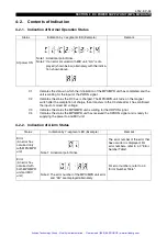
4-2-1. Indication of Normal Operation Status
Eeospcsa2011
4-2-2. Indication of Alarm Status
Eeospcsa2012
Status
Indication by 7-segment LED (Example)
Remark
At power ON
Note 1: A decimal point blinks.
Note 2: If an error cocurred with MIV unit, "AA" is dis-
played (shown below) alternately with the indica-
tion shown above.
C1
: Indicates the status in which the initialization of the MPS/MPR unit has completed and the
unit is waiting for the input of the PWON signal.
C2
: Indicates the status the DC bus is charged. The MPS/MPR unit turns on the magnet
switch after the completion of charge, then transfers to the C3 state after it has confirmed
the input of correct AC voltage.
C3
: Indicates the status the MPS/MPR unit is waiting for the ORPON signal.
C4
: Indicates the status the MPS/MPR unit has received the OPRON signal and is ready for
supplying the power to and MIV unit.
Status
Indication by 7-segment LED (Example)
Remark
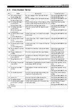
Error
(An error has
occurred only
with MPS/MPR
unit)
Note 1: A decimal point blinks.
The error number of the error that
has occurred is displayed. For
error numbers, refer to 4-3 "Error
Number Table".
Error
(An error has
occurred with
both MPS/MPR
unit and MIV
unit.)
Note 2: The error number of the MPS/MPR unit error
and "AA" are displayed alternately.
For error numbers, refer to 4-3
"Error Number Table".
Artisan Technology Group - Quality Instrumentation ... Guaranteed | (888) 88-SOURCE | www.artisantg.com


