


4742-E P-(i)
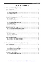
TABLE OF CONTENTS
TABLE OF CONTENTS
SECTION 1 INVERTER UNIT (MIV UNIT) ......................................................................1
1. System Configuration ................................................................................................................... 1
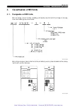
2. Classification of MIV Units ............................................................................................................ 2
2-1. Designation of MIV Units ....................................................................................................... 2
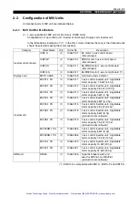
2-2. Configuration of MIV Units..................................................................................................... 3
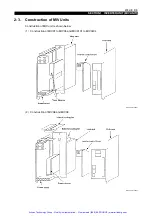
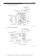
2-3. Construction of MIV Units ...................................................................................................... 6
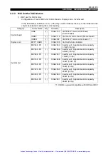
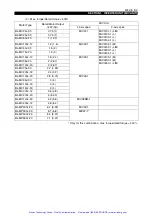
2-4. MIV Unit Selection Tables by Motor Types ........................................................................... 8
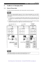
3. Cautions on Changing Units ....................................................................................................... 11
3-1. General Precautions ............................................................................................................ 11
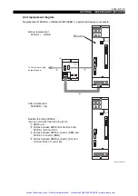
3-2. Unit Replacement Procedure .............................................................................................. 12
4. Indication of Operating Status .................................................................................................... 14
4-1. Arrangement of Status Indicating LED ................................................................................ 14
4-2. Contents of Indication .......................................................................................................... 15
4-3. Error Number Tables ........................................................................................................... 18
5. Controller ID Number.................................................................................................................. 32
6. Description of Waveform Monitor ............................................................................................... 35
6-1. MIV Unit for Feed Axes/Turrets/Machine Axes ................................................................... 35
6-2. MIV Unit for Spindle/M-tool Spindle/Sub Spindle ................................................................ 37
6-3. SWM Monitor Unit ............................................................................................................... 39
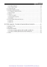
7. Connection.................................................................................................................................. 44
7-1. System Connection ............................................................................................................. 44
7-2. Terminal Block Screw Size .................................................................................................. 46
7-3. Connectors .......................................................................................................................... 46
8. MIV Unit External Dimensions .................................................................................................... 49
8-1. MIV Unit (1-axis Specification) for BL Motors ...................................................................... 49
8-2. MIV Unit (2-axis Specification) for BL Motors ...................................................................... 50
8-3. MIV Unit (1-axis Specification) for VAC Motors ................................................................... 50
SECTION 2 DC POWER SUPPLY UNIT (MPS, MPR UNIT) ........................................60
1. System Configuration ................................................................................................................. 60
2. Classification of DC Power Supply Units .................................................................................... 61
2-1. Designation of DC Power Supply Units ............................................................................... 61
2-2. Configuration of Power Supply Units ................................................................................... 62
2-3. Construction of Power Supply Units .................................................................................... 63
3. Cautions on Changing Units ....................................................................................................... 65
4. Indication of Operating Status .................................................................................................... 67
4-1. Arrangement of Status Indicating LED ................................................................................ 67
Artisan Technology Group - Quality Instrumentation ... Guaranteed | (888) 88-SOURCE | www.artisantg.com


