


4742-E P-13
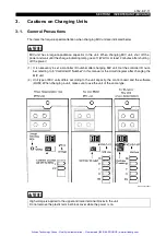
SECTION 1 INVERTER UNIT (MIV UNIT)
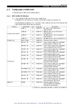
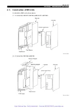
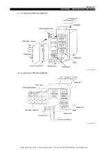
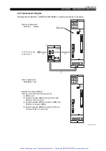
Unit replacement diagram
Replacement of MIV06-1 + DBR8 with MIV06DB-1 is explained here as an example.
EIOSPCSA1041R01
DCA
DCB
BRA
Besides the faulty MID06-1,
remove and collect the following items:
DBR8 unit
Cables between DBR8 terminal block and
Cables between DBR8 connector [DBR] and
Cables between DBR8 connector [DC] and
After replacement
MIV06DB-1 only
XT1(U V W)
U V W
AXIS
UNIT
DC
DBR
UNIT TYPE
DBR8
DCA
DCB
BRA
BAB
To 24 V power supply
inside the panel
Before replacement
MIV06-1 +
DBR8
Failure!
MIV06-1 terminal block
MIV06-1 connector [BRB]
terminal block of control box
Artisan Technology Group - Quality Instrumentation ... Guaranteed | (888) 88-SOURCE | www.artisantg.com


