background image

4. Options Setting 

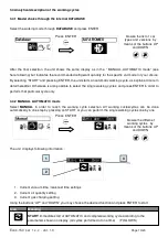
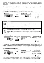
Select OPTIONS, to recall the optional functions : 

Press  ENTER

Browse the different

functions  by means of

the buttons UP and

DOWN

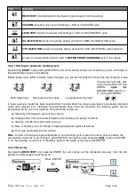
Icon 

Meaning 

YES

PRINT FLIUD: printing option of recovered fluid yes/no

MAX RECOVERY: setting of the “Max recovery” options 

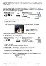
4.1 Printing options of the recovered fluid 

Gives the opportunity to choose, if to print or not the recovered fluid quantity among the other working cycle 
data which are printed by default (recovered quantity yes/no option)

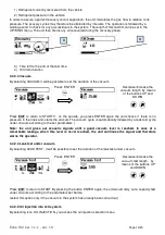
Press  ENTER

Choose YS or NO  by

means of the buttons UP

and DOWN

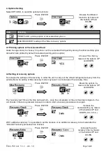
4.2 Setting of recovery options 

To increase the settings of the recovery in order the unit to carry out the utmost refrigerant recovery from the
vehicle (Note: he setting of Max recovery mode may result in an increase of the recovery time) 

Press  ENTER

Brows the options  by

means of the buttons UP

and DOWN

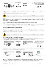
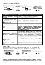
The “

recovery test”

 time is the time during which – once the compressor of the unit has been stopped – the 

unit checks if there is a pressure increase in order to start a recovery procedure once again.

Press  ENTER

Increase the

durationsetting  by means

of the buttons UP and

DOWN (min  3 min.)

With “

additional recovery

” it is possible to set the duration of an additional recovery to be made after the 

“standard” recovery procedure has finished.

Press  ENTER

Increase the extra

recovery time  by means

of the buttons UP and

DOWN

Ecos-150  sw  1.x.x  - ver. 1.0            


Page 16/20

Summary of Contents for ECOS-150

Page 1: ...Use and Instruction Manual Ecos 150 sw 1 x x ver 1 0 Service station for A C systems ECOS 150...

Page 2: ...Analytical description of the working cycles 10 3 4 1 Model choice through the internal DATABASE 10 3 4 2 MANUAL AUTOMATIC mode 10 3 4 2 1 Starting an automatic working cycle 11 3 4 2 2 Recovery 11 3...

Page 3: ...0X Ecos20X HFO 1234YF for Fast20XYF Do not make modifications to the service unit Only employ original spare parts and accessories Use authorized additives or consumables only ask for advice from an a...

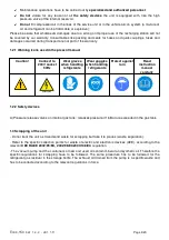
Page 4: ...handling refrigerants Wear goggles when handling refrigerants Protect against rain Read instruction manual carefully 1 2 2 Safety devices A Pressure release valves on internal gas tank releases press...

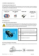
Page 5: ...first time remove the safety screw which is screwed to the tank load cell for protection during transport see fig 1 It is recommended to check the regular functioning of the load cell for example by h...

Page 6: ...the gas residuals in the A C system of the vehicle at the en of the working cycle Note in case of a pressure test which is not preceded by a standard working cycle the user has to recover the gas resi...

Page 7: ...t used by the A C system to be serviced is the one the service unit is intended for R134a Check oil levels vacuum pump and new oil reservoir After having turned on the unit check the level of the refr...

Page 8: ...databank update 9 Button EXIT To select and confirm the different functions or to enter the following menu 10 Button ENTER Interrupts any whatsoever operation to exit and return to the previous menu 1...

Page 9: ...ease of Non Condensable Gases If the value of the theoretical gas pressure see above point c calculated on the base of the gas temperature measured by the temperature probe is significantly higher tha...

Page 10: ...ycles and press ENTER in order to perform that particular cycle only 3 4 2 MANUAL AUTOMATIC mode Select MANUAL in order to reach the working cycle selection All working cuclescycles can be done automa...

Page 11: ...igh pressure only open Low pressure only open In case a vehicle model has been selected from the data bank the various parameters are already indicated under their relevant icon otherwise the paramete...

Page 12: ...it checks if there is no pressure in the lines and starts the vaccum The vacuum cycle is automatically followed by a leak test cycle under vacuum according to the set parameters Note the unit gives ou...

Page 13: ...and DYE INJECTION it is possible to set the quantity of dye liquid to be injected into the A C system The procedure is similar to that used for the oil charging see aboveI Once set the parameters pres...

Page 14: ...R134a LOAD CELL TEST access to the display relevant to the various load cells test REPORT PRINT report printing on recovered refrigerant and oil quantity and injected by the unit 3 4 3 1 Self recycli...

Page 15: ...balance in order to test the weight measurement in order to calibrate the load cell follow the specific instructions in the service manual 3 4 3 4 Printing of refrigerant management report Press ENTE...

Page 16: ...ttings of the recovery in order the unit to carry out the utmost refrigerant recovery from the vehicle Note he setting of Max recovery mode may result in an increase of the recovery time Press ENTER B...

Page 17: ...of the opening time of the oil injection valve according to higher lower viscosity of oil to be injected and to the environment temperature This regulation is only necessary for models without oil sc...

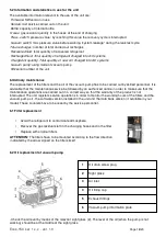
Page 18: ...sable that the maintenance service be followed by an authorized centre in order to make sure that the maintenance operations are carried out in a correct way so that the warranty of the product is not...

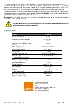
Page 19: ...pump is a special waste and as such it has to be scrapped according to the regulations in force Warning switch off the unit and unplug from electrical socket before operating on the vacuum pump Elect...

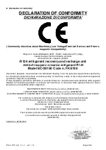
Page 20: ...ribuita in accordo totale con i requisiti essenziali specificati dalle seguenti Direttive Comunitarie riguardanti la sicurezza dei macchinari la sicurezza delle apparecchiature in bassa tensione e la...

Reviews: