41356801TH Rev.1
37 /
2.3.4
Revision of LED Head Illumination
An LED correcting head, which is capable of correcting the illumination of the LED for each dot, is being
used in this printer. LED illumination correction function of 16 steps is carried out by using an EEPROM
which is installed in the LSI that maintains the LED illumination correction values, and an LED correction
drivers together as a pair.
The printing and correction data obtained from the CPU through four signal lines are sent to the LED
array.
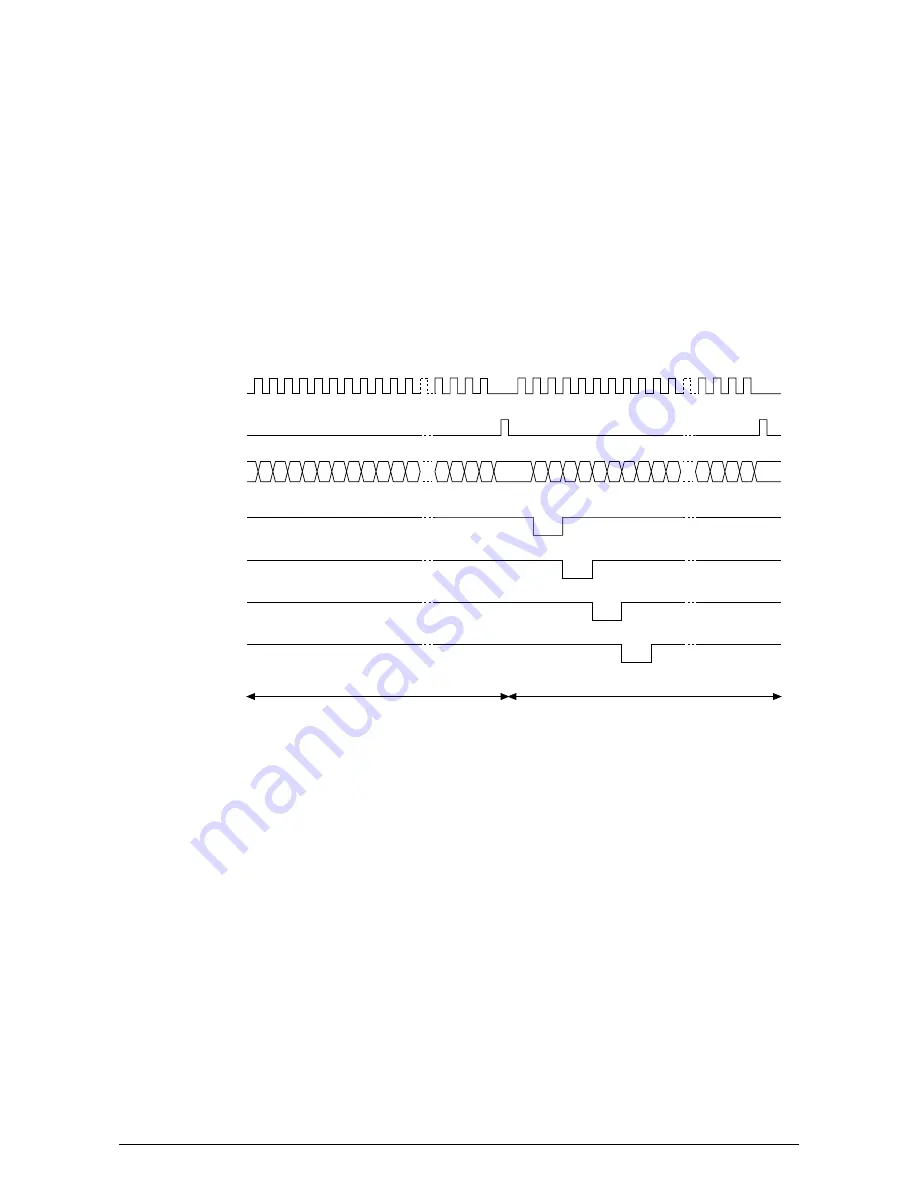
The printing operation timing chart is shown below.
The printing operation is carried out in normal mode. Under ordinary circumstances such as when the
power is turned on or when LOADI signal level is low, the normal mode is enabled.
The printing operation is carried out in the following sequence. First, the printing data DATAI3 through
DATAI0 are stored, sequentially shifted, in the shift registers of the LED drivers, by the printing data
synchronous clock, CLOCKI. Then the printing data stored in shift registers are latched by the high level
pulse of LOADI. The latched printing data turns the LEDs on by STRB1I-N through STRB4I-N and
actuates printing.
CLOCKI
LOADI
DATAI3~0
STRB1I-N
STRB2I-N
STRB3I-N
STRB4I-N
Normal Mode Printing Timing Chart
First line printing data sent
Second line printing data sent
First line printing
Summary of Contents for OKIPAGE 14
Page 46: ...41356801TH Rev 1 46 Upper cover unit Figure 3 2 Upper cover ...
Page 129: ...41356801TH Rev 1 129 Figure 8 2 Upper cover unit 1 ...
Page 174: ...41356801TH Rev 1 174 5 2 PCB Layout OLEV 11 PCB CN3 CN2 SEN2 ...
Page 175: ...41356801TH Rev 1 175 6 PARTS LIST Figure 6 1 Multi Purpose Feeder 9 5 7 6 4 1 2 3 8 ...
Page 190: ...41356801TH Rev 1 190 CONTROLLER MOTOR DRIVER SEN2 SEN1 OSC PU MOTOR 5 2 PCB Layout TQSB 2 PCB ...
Page 191: ...41356801TH Rev 1 191 Figure 6 1 High Capacity Second Paper Feeder 1 2 4 3 5 6 PARTS LIST ...
Page 194: ...41356801TH Rev 1 194 SECTION1 CABINET CASSETTE ASSEMBLY 5 6 3 2 4 7 8 1 iv iv i i ...


