© 2015 OJ Electronics A/S
BR965A09a
BR1025A13a
BR1025A13a
© 2015 OJ Electronic
A/
S
WLOC 3
Master
34
introduction
WLM3-xFS masters are supplied pre-prepared for weather compensation, and simply by adding an
outdoor compensation module on the 2-wire bus and a temperature sensor on the supply water side,
your control system can be weather compensated. Preset values are factory programmed but can
easily be adjusted according to local needs via the display on the master. See the “Master with Display
- Type WLM3” user manual for instructions on changing of the default factory settings.
installation
The unit should be mounted under the eaves of the roof or, alternatively, 2-3 metres above ground
level. Direct sunlight or other heat sources, e.g. ventilation vents, must be avoided. The unit should
be mounted vertically with the cable entry downwards.
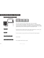
Bus connection
Only OJ units which are suitable for two-wire communication can be used.
Standard installation cable of minimum 2 x 0.25 mm² can be used. Units can be connected in
conventional star formation or in bus mode (daisy chain).
The master has 4 sets of terminals marked SENSOR/CONTROLLER BUS that can be used for
connecting the 2-wire signal cable from the unit.
There are 4 identical sets of terminals for convenient installation. Any unit can be connected to any pair
of terminals. The total length of the 2-wire system can be up to 300 m with a maximum length of 100
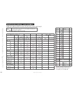
m between any two units. For further information, see the table below.
Remember to c to + and – to – .
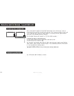
Waterline outdoor Compensation Module - type WloC3
technical specifications
See the Waterline Outdoor Compensation Module Instructions.
Summary of Contents for WLCT3
Page 55: ...2015 OJ Electronics A S 55...


