4-9
CHAPTER 4 REPAIR PROCEDURES
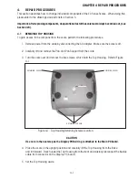
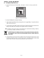
Figure 4-14. Load Cell Retaining Screw Locations.
4.4
REPLACING THE LOAD CELL ASSEMBLY (WITH FRAME)
The Load Cell Assembly is centrally located inside the scale. The Load Cell is factory assembled and the
overload protection stops are installed. The overload protection stops should be checked before
installation.
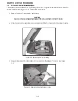
1. Refer to Section 4.1 and remove Top Housing.
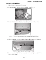
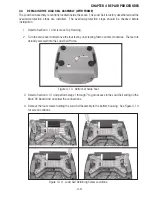
2. Turn the scale over and remove the four feet by unscrewing them counter-clockwise. The feet are
actually screwed into the Load Cell Frame.
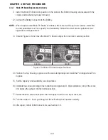
3. Refer to Section 4.3.1 and perform steps 1 through 7 to gain access to the Load Cell wiring on the
Main PC Board and unsolder the connections.
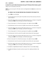
4. Remove the four screws holding the Load Cell Assembly to the bottom housing. See Figure 4-14
for screw locations.
Figure 4-13. Bottom of Scale Feet.
Summary of Contents for EC Series
Page 2: ......
Page 4: ......
Page 14: ...2 6 CHAPTER 2 DIAGNOSIS...
Page 30: ...3 16 CHAPTER 3 SCALE TESTING AND CALIBRATION...
Page 52: ...A 4 APPENDIX A SERVICE MODES...
Page 55: ......
Page 56: ...PN 80010584 B SERVICE MANUAL EC SERIES SCALES 80010584...

