2021-03-23 / Rev. 10
VV016042
113
13.4
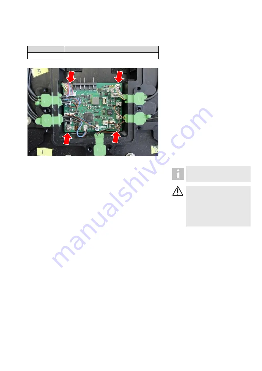
Pedal PCB
VX541135
Quantity
Description
1
Pedal PCB
STEP 1:
1.
2.
3.
4.
5.
Open pedal housing according to
the procedure described in
Remove battery pack according to
Take a photo of the connected ca-
bles.
Disconnect all cables.
Release PCB by removing 4
screws.
When mounting the new print take
care that you plug in the cables ac-
cording to the photo.
After this procedure, the pedal
must be paired with the unit.
CAUTION!
Incorrect pedal signals trans-
ferred to device
Faulty operation of device
► After this procedure, the pe-
dal needs recalibrating ac-
cording to
Summary of Contents for OS 4
Page 1: ......
Page 44: ...2021 03 23 Rev 10 VV016042 44 10 2 Core PCB ...
Page 134: ...2021 03 23 Rev 09 VV016042 134 18 Appendix C Safety check Please see form on next page ...
Page 136: ...2021 03 23 Rev 09 VV016042 136 19 Appendix D Functional test Please see form on next page ...
Page 151: ...VV016042 2021 03 23 Rev 10 ...


