background image


19

Ocmis Irrigazione S.p.A.   – INSTRUCTION AND WARNING MANUAL – Translation of Original Instructions 
MUMR-R1.02  .EN - 31/07/2015

CHAPTER 2 - Technical specifi cations and layout

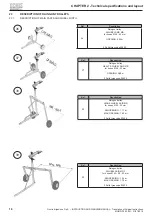
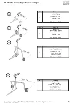
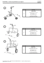
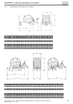
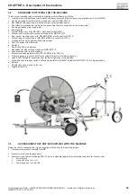
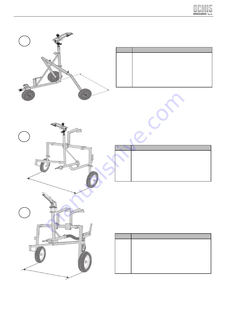
Ref.

Description

41

Raingun trolley 

2 SKID WHEELS R1AT15

for hoses Ø 1.96 – 2.28 - 2.48 in

MIN OPENING: 5.25 ft

MAX OPENING: 6.89 ft

2 Solid tyres code 00425

Ref.

Description

42

Raingun trolley 

3 WHEELS   R1AT15

for hoses Ø 1.96 – 2.28 - 2.48 in

MIN OPENING: 4.10 ft

MAX OPENING: 5.58 ft

2 Solid tyres code 00435

1 Pneumatic wheel code 00405

40

MIN - M

AX

41

42

MIN - M

AX

MIN - M

AX

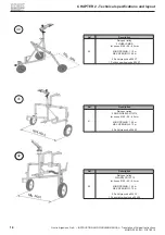
Ref.

Description

40

Raingun trolley 

3 WHEELS   MRR

for hoses Ø 1.96 – 2.28 - 2.48 in

MIN OPENING: 3.77 ft

MAX OPENING: 5.25 ft

2 Solid tyres code 00437

1 Solid nose wheel code 00437

Summary of Contents for MR

Page 1: ...30 11 2015 EN Models MR MR 1 Models MRR R1AT15 INSTRUCTIONS AND WARNING MANUAL HOSE REEL TRAVELLING RAINGUNS MUMR R1 02 EN...

Page 2: ...EC Directive on the approximation of the laws of Member States relating to machinery The Manufacturer would like to thank you for purchasing one of its products and recommends reading this manual and...

Page 3: ...ing plates Chapter 5 Transport and Installation Packaging and transport Assembly and placement Connections Checks and inspections after installation Chapter 6 Use and Operation Preliminary information...

Page 4: ...DESCRIPTION OF CONTROLS 24 2 5 1 MECHANICAL CONTROLS ON THE MACHINE 24 2 5 2 COMPUTER CONTROLS 26 3 MACHINE DESCRIPTION 27 3 1 INTENDED USE 27 3 2 UNAUTHORISED USE 27 3 3 MACHINE DESCRIPTION 28 3 4 S...

Page 5: ...ON 58 6 1 PROFESSIONAL PROFILES AND MANDATORY PPE 58 6 2 CHECK PRIOR TO STARTING WORK 58 6 2 1 PREOPERATIVE INSPECTION 58 6 2 2 FUNCTIONAL TESTS WITH REELED IN HOSE AND MACHINE STATIONARY 59 6 2 2 1 T...

Page 6: ...ION 85 7 8 2 LIST OF MAINTENANCE SHEET AND FREQUENCY 86 7 8 2 1 EVERY 200 HOURS 86 7 8 2 2 BEFORE STORAGE AT THE END OF THE SEASON 86 7 8 2 3 EVERY YEAR BEFORE THE START OF THE IRRIGATION SEASON 87 7...

Page 7: ...orth by speci c European and or national laws in force Use of trailer or transfers on public roads without Road Use Approval Exceptional events Responsibility for the application of the safety require...

Page 8: ...sure the utmost operating reliability the Manufacturer has performed careful selection of the materials and components to be employed in constructing the machinery submitting it to proper testing befo...

Page 9: ...out in the various chapters of the manual have the purpose of de ning behaviour and a set of obligations one should adhere to in performing the various activities in order to operate under safe condit...

Page 10: ...TEM ACTUATION DEVICE Mechanism that powers the guide system assuring even winding of the hose in layers Ref 3 5 EN 908 COVER AREA Range of various turret positions corresponding to all possible orient...

Page 11: ...agrams and to check the correct functional cycle They are able to work on live electrical boards junction boxes control equipment etc only if they are suitable Instructed Person See EN50110 1 Where ne...

Page 12: ...signs and areas displaying this symbol and do not access areas thus signalled unless the area in question has had supply lines and or power pre emptively removed 60209 Crushing hazard do not stand be...

Page 13: ...harge user It is mandatory to keep a safe distance during the operation of the rear stabilisers and ensure no one can come into contact with them Pay the utmost attention to the signs and areas where...

Page 14: ...es or electrical control units and in any case in any area where this sign is displayed All prohibitions in force in the country of use of the machine plant remain valid as well as internal facility o...

Page 15: ...rom those responsible Symbol Meaning Notes Code Manufacturer Use of the protective helmet is mandatory Indicates a mandatory requirement for maintenance personnel to use the protective helmet PPE to b...

Page 16: ...compartments and or control and power units during operation or immediately after switching off DANGER The safety guards and devices must be maintained in perfect working order so that they operate co...

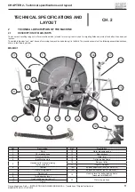
Page 17: ...g it in the eld The machine consists of the following assemblies sections shown in the Drawing below MR MR 1 Ref Description Ref Description 1 Reel 12 Water pressure gauge 2 PE irrigation hose 13 Rear...

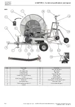
Page 18: ...ors 3 Document holder 14 Water inlet 4 Identi cation plate 15 Trolley loading frame 5 Handwheel for manual winding 16 Raingun trolley 6 Tow bar 17 Irrigator Raingun 7 Manually operated front stabilise...

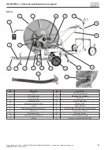
Page 19: ...holder 14 Water inlet 4 Identi cation plate 15 Trolley loading frame 5 Handwheel for manual winding 16 Raingun trolley 6 Tow bar 17 Irrigator Raingun 7 Manually operated front stabiliser leg 18 Winch...

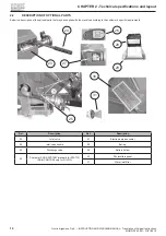
Page 20: ...description of the optional parts that may be supplied with the machine according to the customer s speci c requirements Ref Description Ref Description 23 Inlet valve 27 Electronic metre counter 24...

Page 21: ...AND WARNING MANUAL Translation of Original Instructions MUMR R1 02 EN 31 07 2015 CHAPTER 2 Technical speci cations and layout Ref Description Ref Description 32 Internal combustion engine 34 Pump 33 F...

Page 22: ...MR for hoses 40 43 mm OPENING 0 92 m 2 Solid tyres code 00449 Ref Description 37 Raingun trolley HEAVY 2 WHEEL SKID MR for hoses 40 43 mm OPENING 0 88 m 2 Solid tyres code 00436 Ref Description 38 Rai...

Page 23: ...s code 00449 Ref Description 37 Raingun trolley HEAVY 2 WHEEL SKID MR for hoses 1 57 1 69 in OPENING 2 89 ft 2 Solid tyres code 00436 Ref Description 38 Raingun trolley HIGH 2 WHEEL SKID MR for hoses...

Page 24: ...m MIN OPENING 1 15 m MAX OPENING 1 60 m 2 Solid tyres code 00437 1 Solid nose wheel code 00437 Ref Description 41 Raingun trolley 2 SKID WHEELS R1AT15 for hoses 50 58 63 mm MIN OPENING 1 60 m MAX OPEN...

Page 25: ...in MIN OPENING 5 25 ft MAX OPENING 6 89 ft 2 Solid tyres code 00425 Ref Description 42 Raingun trolley 3 WHEELS R1AT15 for hoses 1 96 2 28 2 48 in MIN OPENING 4 10 ft MAX OPENING 5 58 ft 2 Solid tyre...

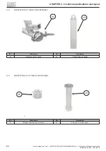
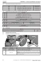
Page 26: ...R 2 Technical speci cations and layout 2 3 2 DESCRIPTION OF THE MAIN ACCESSORIES 43 44 Ref Description Ref Description 43 Discharge cap for trolley 44 Trolley balancing ballast 2 3 3 DESCRIPTION OF OP...

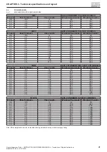
Page 27: ...5 58 4 2 140 407 678 58 4 2 148 413 699 63 4 5 80 373 556 63 4 5 100 390 619 63 4 5 110 398 650 MRR with 2 STANDARD 20X10 0X8 2PR WHEELS hose Hose thickness Hose length Weight without water Weight wit...

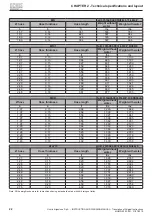
Page 28: ...0 1 365 2 48 0 18 361 877 1 433 MRR with 2 STANDARD 20X10 0X8 2PR WHEELS hose Hose thickness Hose length Weight without water Weight with water in in ft lbs lbs 1 97 0 15 394 1 265 1 642 1 97 0 15 492...

Page 29: ...ARD in 42 13 43 70 49 60 76 77 59 06 MR 1 2 Wheels um A B C D E 16 6 50 X 8 STANDARD cm 112 114 162 270 190 16 6 50 X 8 STANDARD in 44 09 44 688 63 78 106 30 74 80 MRR 2 Wheels um A B C D E F G 20 X 1...

Page 30: ...D WHEEL 516 x 140 mm 20 31 x 21 26 in code Solid nose wheel for MRR 00437 SOLID WHEEL 4 00 x 4 295 x 100 mm 11 61 x 3 94 in code Pneumatic Pivoting Wheel In ation pressure 00405 13 5 00 x 6 4PR 320 12...

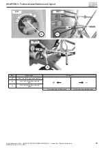
Page 31: ...s MUMR R1 02 EN 31 07 2015 CHAPTER 2 Technical speci cations and layout 50 MR 51 MR 1 52 MRR Ref Description Function 50 Knob to adjust by pass opening MR 51 Knob to adjust by pass opening MR 1 52 Kno...

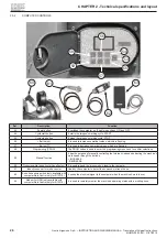
Page 32: ...58 Programming PROG The PROG button is used to enter the programming menus and to con rm selections 59 Manual function It has the purpose of manually controlling the turbine by pass and adjusting the...

Page 33: ...s and raingun trolley do not tow the machine at speeds exceeding 10 km h and in any case at lower speeds depending on the type of terrain muddy potholes slopes etc present at the site do not move the...

Page 34: ...been properly positioned The hose is then reeled back in mechanically Once the raingun trolley has been properly positioned on the surface to be irrigated the operating logic entails conveying the pr...

Page 35: ...15 Manual raingun trolley lifting for MR MR 1 MRR with winch for R1AT15 Flanged turbine on the gearbox tted with by pass Set of 3 nozzles with different Gearbox Power take off on the gearbox Handwheel...

Page 36: ...al power supply 3 Flow meter error 4 Speed fault 5 No pressure 6 Work run end 7 It lets you know the metres of unwound hose reeling in speed and work run end time 8 It also allows you to send the Stop...

Page 37: ...e recommended ones may cause accidents risks and are forbidden 4 1 1 PERSONNEL TRAINING CAUTION The hose reel travelling raingun is a farm machine which is towed for moving it and is used for irrigati...

Page 38: ...rmed a risk assessment with the aim of assessing compliance with the essential health and safety requirements set forth in Directive 2006 42 EC as well as the tests and inspections set forth by the ap...

Page 39: ...ference to the following regulatory provisions EN ISO 12100 EN 908 EN 1553 EN 953 EN ISO 13857 EN ISO 4413 It also declares It is the Customer s responsibility to check and if necessary adapt the new...

Page 40: ...ent for outdoor use procedure as per Annex V Item 2 Measured sound power level LwA 103 Db A Guaranteed sound power level LwA 104 Db A and with special reference to the following regulatory provisions...

Page 41: ...on DANGER Special attention should be paid to positioning the machine on stable ground Use of the machine on land with a grade exceeding 8 5 degrees is forbidden DANGER The hazardous areas must be acc...

Page 42: ...protective measures in compliance with the laws of the country of installation and use of the machine The operator working near the machine with internal combustion engine is required to use personal...

Page 43: ...e are responsible for their disposal either directly or through rms authorised agencies or by transferring the waste to the entities running the public service with whom an agreement has been entered...

Page 44: ...ction devices consist of xed guards that have the purpose of preventing access to the various moving parts of the machine during operation The machine is tted with xed covers which are located in area...

Page 45: ...al pressure may be present on actuator components engine cylinders gears coil etc and on piping which in the event of operations on the component might lead to hazardous situations Before any operatio...

Page 46: ...the machine s ducts If the machine s hoses are pressurised never release the caps as they might be ejected violently if the internal pressure is not released Risk of violent impact with the pressuris...

Page 47: ...ing it is not equipped with any kind of lighting system The machine is not equipped with a lighting system For night time use or in the event of insuf cient visibility the user must provide a lighting...

Page 48: ...ackages from the truck from the container or from the case opening the packages handling parts expose operators to the suspended loads and crushing hazard The same risk exists throughout all subsequen...

Page 49: ...nd factory settings DANGER Never aim the raingun s water jet at persons animals or property other than for the purposes the machine has been constructed for Failure to comply with this requirement may...

Page 50: ...eld Should acid be accidentally ingested do not drink any substances and do not induce vomiting for any reason Do not panic and go to the emergency services for the required checks Indicating the inge...

Page 51: ...any kind of operation on the internal combustion engine and or components controlled by it it is indispensable for The engine to be off and cold The engine and or hydraulic oil to be cold and not pres...

Page 52: ...some case where provided use the ballasts supplied with the trolley Failure to comply with the above requirements and the requirements expressly set out in all chapters of this Manual may entail forfe...

Page 53: ...cmis Irrigazione S p A INSTRUCTION AND WARNING MANUAL Translation of Original Instructions MUMR R1 02 EN 31 07 2015 CHAPTER 4 Safety 4 8 POSITION AND MEANING OF THE OPERATION PICTOGRAMS MR MR 1 MRR R1...

Page 54: ...48 Ocmis Irrigazione S p A INSTRUCTION AND WARNING MANUAL Translation of Original Instructions MUMR R1 02 EN 31 07 2015 CHAPTER 4 Safety 4 9 POSITION AND MEANING OF THE WARNING PICTOGRAMS MR MR 1...

Page 55: ...49 Ocmis Irrigazione S p A INSTRUCTION AND WARNING MANUAL Translation of Original Instructions MUMR R1 02 EN 31 07 2015 CHAPTER 4 Safety MRR R1AT15...

Page 56: ...tive gear complete with self contained breathing apparatus with face shield suitable re protection clothing including helmets protective boots and gloves All the above in compliance with European Stan...

Page 57: ...red to the Customer with some disassembled parts such as wheels water inlet pipe raingun trolley and or others The Manufacturer or whoever acts on their behalf shall complete the assembly of the disas...

Page 58: ...e requirements for all activities such as maintenance connection inspection as well as any transit areas escape routes etc in compliance with applicable regulations and laws in the installation site a...

Page 59: ...fety shoes Ropes and chains should always be checked before using them as well as periodically It is forbidden to walk drive under suspended loads The operational area must be kept as clear as possibl...

Page 60: ...s set out above you may proceed with lifting for placement ensuring the base remains level during lifting and is not subject to swinging or unbalancing After perfect balancing is achieved you may proc...

Page 61: ...rosswise on slopes as this might lead to the machine overturning In any event never travel on grades exceeding 8 5 DANGER OF HITTING PERSONS OR PROPERTY Prior to performing any machine movement ensure...

Page 62: ...e assemblies the machine consists of ensuring there are no special mechanical abnormalities foreign matter in operating areas and that all components actuators raingun trolley etc are properly fastene...

Page 63: ...there may be residue such as oil battery acid or fuel in the engine tank Additional information concerning disassembly of trade parts such as the battery engine etc is provided in the relevant manuals...

Page 64: ...perform their function Improper use of safety systems and devices may cause serious injury or death CAUTION PPE REQUIRED TO OPERATE THE MACHINE Every operator s undivided attention is required to oper...

Page 65: ...e machine 1 MANUALLY ACTUATED FRONT STABILISER LEG For MR MR 1 Lift the tow bar so its lower part is able to be anchored to the ground see ref 6 par 2 1 and hook the chain onto the frame For MRR R1AT1...

Page 66: ...the factory entails for computer less machines the top part of the corrector touches the hose for machines with computer the top part of the corrector is tangential to the outer reel diameter MR MR 1...

Page 67: ...ide its lifting area While unwinding the hose ensure the pinion located on the gearbox output shaft meshes properly with the gear on the side of the reel maximum clearance tolerance between 1 2 mm 0 4...

Page 68: ...57 1 69 in Ref 36 37 38 par 2 3 1 3 2 WHEEL TROLLEY SLIDE MR 1 FOR HOSES 50 58 63 mm 1 97 2 28 2 48 in Ref 39 par 2 3 3 WHEEL TROLLEY MRR FOR HOSES 50 58 63 mm 1 97 2 28 2 48 in Ref 40 par 2 3 1 2 3...

Page 69: ...ws closer to or away from the exible rod on the micro switch 5 CHECKS TO BE PERFORMED FOR MACHINES EQUIPPED WITH ELECTRONIC METRE COUNTER OPTIONAL FEATURE Check correct cylinder distance inductive sen...

Page 70: ...r controlled ELECTRICAL VALVES a COMPUTER CONTROLLED ELECTRICAL INLET VALVE Before connecting water inlet to the pumping station simulate end of work with the computer CO and ensure the same enables s...

Page 71: ...or ensure that the tractor has the required power and capacity to tow the machine the tyres of the machine are in ated see par 2 4 3 ONLY FOR MRR andR1AT15 insert the safety pin to stop turret rotatio...

Page 72: ...aim it as straight as possible with respect to the hose unwinding direction 5 only for MRR and R1AT15 insert the rotation stop pin in the seat of the spokes on the traveller and closest to the chosen...

Page 73: ...ef 36 37 38 39 40 par 2 3 1 ensure the cover on the bend of the hose at the head of the trolley is screwed on 2B For skid and 3 wheel trolleys see ref 41 42 par 2 3 1 ensure the cover is engaged and c...

Page 74: ...agged the reel might violently turn in the opposite direction It is therefore essential to pay the utmost attention in ensuring no people are near the machine 6 6 1 ADJUSTMENT OF AUTOMATIC SPEED CORRE...

Page 75: ...oping on the reel 4 Actuate power take off rotation from the tractor paying attention to the direction of rotation and maximum number of RPMs which must not exceed the limit of 540 g 1 5 Rapid hose re...

Page 76: ...r to moving the machine it is essential to ensure the pumping station has automatically switched off at the end of work or has been intentionally shut off to interrupt operation Consequently the valve...

Page 77: ...ATIONS FOR COMMISSIONING Regularly ll the tank at the side of the machine through the suitable inlet mouth tted with cap Never use the tank on the engine for any reason Connect the water inlet hose to...

Page 78: ...able pull rope Note The engine only starts if the machine is pressurised Move the air control lever to the work position by pushing it to the right Accelerate the engine with the suitable lever until...

Page 79: ...2 4 6 10 7 PRECAUTIONS FOR ENGINE AND PUMP During operation of the motor pump do not stand close to parts operating at high temperature even if tted with suitable guards exhaust manifold and muf er as...

Page 80: ...irective 2006 42 EC Machinery Directive de nes Operator as the Person quali ed to install operate adjust clean and perform maintenance on the machine The de nitions of professional pro les set out by...

Page 81: ...e of machine maintenance must be well trained and have thorough knowledge of accident protection rules Unauthorised personnel must remain outside the maintenance work area during operations The safety...

Page 82: ...emoval of jammed machine parts disconnect and padlock lock all power sources and discharge all uid power systems Keep away from holes nozzles and or bleed cocks during operations to discharge circuit...

Page 83: ...ervals Ensure machine parts are correctly lubricated Insuf cient or faulty lubrication may cause damage and malfunctions Prior to starting check and maintenance operations it is recommended to remove...

Page 84: ...ly dangerous and harmful since they may damage the skin and enter the bloodstream or hit your eyes in the event of contact That is why appropriate gloves and goggles should always be worn during inspe...

Page 85: ...as well as constant maintenance During tyre tting and removal operations certain safety precautions need to be adhered to in order to prevent possible errors and carelessness which may cause serious i...

Page 86: ...the wheel Lubricate the parts of the wheel in contact with the heel and the inner tube Removing rims from the wheels Prior to starting disassembly of a wheel of the vehicle ensure the tyre is complete...

Page 87: ...contact with cleaning liquids and inhaling their vapours Avoid using them near naked ames or heat sources assure adequate ventilation in the site of utilisation Besides using the usual caution during...

Page 88: ...nd be inalterable to ageing They must not damage the material which scraper rings joints rubber plastic parts and paint of the machine are ib contact with Continue using the lubricants used upon rst u...

Page 89: ...ION AND WARNING MANUAL Translation of Original Instructions MUMR R1 02 EN 31 07 2015 CHAPTER 7 Maintenance 7 7 3 MACHINE PARTS TO BE LUBRICATED WITH GREASE MR MR 1 A L A C D E H I L D C I H E N N grea...

Page 90: ...S p A INSTRUCTION AND WARNING MANUAL Translation of Original Instructions MUMR R1 02 EN 31 07 2015 CHAPTER 7 Maintenance MRR R1AT15 A L F G M B A B C D E F G H I L D C I H E N M N greasing nipples tt...

Page 91: ...ed from the manual and are to be exclusively carried out by the T S C which have the technical knowledge documentation and equipment required to perform the activities DANGER Maintenance operations de...

Page 92: ...paragraph 7 7 3 Inject the speci c product with grease pump see pos 2 paragraph 7 7 1 in positions E F G H paragraph 7 7 3 Spread the speci c grease with paintbrush or spatula see pos 2 paragraph 7 7...

Page 93: ...graph 6 2 7 8 3 MAINTENANCE INFORMATION ON OPTIONAL ACCESSORIES 7 8 3 1 DISCHARGE VALVE Before storage at the end of the season the lter containment box must be unscrewed and it must be emptied from r...

Page 94: ...ginning of chapter 8 If the foreign body is not signi cantly large it may be removed by acting as follows Hook the ratchet chain ref 69 par 2 6 1 to the hook X so the reel is free to rotate right and...

Page 95: ...the nozzle inserted in the turbine water inlet with a 4 mm 0 16 in of smaller internal diameter to do so act as described in the previous case the operating pressure is too low Check the actual press...

Page 96: ...hose and wet ground and or a certain type of crop might abnormally overload reaction on the anchors Remove the hazard situation by acting as indicated in the danger provision at the beginning of chap...

Page 97: ...rt send a request to the Manufacturer indicating the amount and description of the spare part you wish to order The desired spare parts may also be ordered directly from the the Manufacturer s website...

Page 98: ...INSTRUCTION AND WARNING MANUAL Translation of Original Instructions MUMR R1 02 EN 31 07 2015 CHAPTER 10 Spare Parts SPARE PART ORDERING FORM From To Delivery on To Date Order number MACHINE CODE NAME...

Page 99: ......

Page 100: ...OCMIS IRRIGAZIONE S p A Headquarters and Production Facility 41014 CASTELVETRO MO ITALIA Via S Eusebio 7 Tel 39 059 702150 Fax 39 059 702153 www ocmis irrigazione it info ocmis irrigazione it...

Reviews: