BA_AIR_80_C13A_AIR_80_C22A_OTE3_SW5x_EN_V07.docx
Page 66 of 68
15
Directory of Illustrations
Fig. 1:
Schematic diagram of the refrigerant circuit
............................................................................................................... 5
Fig. 2:
Titling dimension of the heat pump
........................................................................................................................... 6
Fig. 3:
Minimum clearance to the sides.
............................................................................................................................... 7
Fig. 4:
Minimum clearances to front and rear.
...................................................................................................................... 7
Fig. 5:
Installation variant not permitted
.............................................................................................................................. 7
Fig. 6:
Minimum clearances to wall for VHS 80
..................................................................................................................... 8
Fig. 7:
Minimum clearances to wall for two VHS-M 80, installation variant 1
........................................................................... 8
Fig. 8:
Minimum clearances to wall for two VHS-M 80, installation variant 2
........................................................................... 8
Fig. 9:
Minimum clearance to ceiling (VHS 80, VHS-M 80)
...................................................................................................... 8
Fig. 10:
Installation with gravel bed and drainage pipe
....................................................................................................... 8
Fig. 11:
Installation on a flat roof
...................................................................................................................................... 9
Fig. 12:
Hydraulic and electrical connections to the heat pump (schematic)
......................................................................... 9
Fig. 13:
Installing the flow sensor
................................................................................................................................... 10
Fig. 14:
Installing a non-buried connecting pipework, using an AIR 80 C13A with a VHS 80 as an example.
............................ 11
Fig. 15:
Installation shaft
............................................................................................................................................... 12
Fig. 16:
Symmetrical arrangement of buried connection pipework with the installation shaft with AIR 80 C22A.
................... 12
Fig. 17:
Schematic diagram of buried connection pipework with the installation shaft with AIR 80 C22A.
.............................. 13
Fig. 18:
Distribution of the liquid pipework for two VHS-M 80 evaporators
........................................................................ 14
Fig. 19:
Distribution of the suction gas pipework with a Venturi distributor for two VHS-M 80 evaporators
........................... 14
Fig. 20:
Pipework lengths and max. height difference between the heat pump and the evaporator: Case 1
.......................... 15
Fig. 21:
Pipework lengths and max. height difference between the heat pump and the evaporator: Case 2
.......................... 15
Fig. 22:
Max. connecting pipework head of 2.5 mm
......................................................................................................... 16
Fig. 23:
Electrical connection to the heat pump
............................................................................................................... 17
Fig. 24:
Utility signal contact
.......................................................................................................................................... 20
Fig. 25:
Basic control panel
............................................................................................................................................ 23
Fig. 26:
Inside unit dimensions: Heat pump AIR 80 C13A and AIR 80 C22A (in mm)
............................................................. 32
Fig. 27:
Evaporator dimensions: Heat pump VHS 80 with AIR 80 C13A (in mm)
................................................................... 33
Fig. 28:
Evaporator dimensions: Heat pump VHS-M 80 with AIR 80 C22A
........................................................................... 34
Fig. 29:
Point foundation for VHS 80 evaporator (in mm)
.................................................................................................. 35
Fig. 30:
Strip foundation for VHS 80 evaporator (in mm)
.................................................................................................. 35
Fig. 31:
Point foundation for VHS-M 80 evaporator (in mm)
............................................................................................. 36
Fig. 32:
Strip foundation for VHS-M 80 evaporator (in mm)
.............................................................................................. 37
Fig. 33:
Fitting de-icing sensors TQE and TQA
.................................................................................................................. 38
Fig. 34:
Heating rating AIR 80 C13A and AIR 80 C22A
....................................................................................................... 39
Fig. 35:
Heating rating AIR 80 C13A and AIR 80 C22A
....................................................................................................... 39
Fig. 36
:
COP AIR 80 C13A and AIR 80 C22A
...................................................................................................................... 39
Fig. 37:
Limits of deployment for AIR 80 C13A and AIR 80 C22A
........................................................................................ 40
Fig. 38:
Pump characteristic curve Stratos Para 65/ 1-12
.................................................................................................. 41
Fig. 39:
Reading flow rate
.............................................................................................................................................. 42
Fig. 40:
Wiring diagram AIR 80 C13A
.............................................................................................................................. 43
Fig. 41:
Wiring diagram AIR 80 C22A
.............................................................................................................................. 44
Fig. 42:
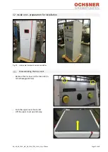
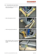
Heat pump transport on wooden palettes
........................................................................................................... 57
16
Directory of Tables
Table 1:
Wiring cross sections
......................................................................................................................................... 18
Table 2:
List of cables for evaporator (values in mm²)
....................................................................................................... 18
Table 3:
Error report table
.............................................................................................................................................. 27
Table 4:
Performance data AIR 80 C13A All performance data to EN 14511 -
∆T 5K (EN255
-
∆T 10K);
.................................... 29
Table 5:
Performance data AIR 80 C22A All performance data to EN 14511 -
∆T 5K (EN255
-
∆T 10K);
.................................... 30
Table 6:
ErP-Product data AIR 80 C13A
............................................................................................................................ 31
Table 7:
ErP-Product data AIR 80 C22A
............................................................................................................................ 31
Table 8:
Heat use pump flow rates for AIR 80 C13A and AIR 80 C22A
.................................................................................. 40
Table 9:
Heat use system nominal flow rate
..................................................................................................................... 42
Summary of Contents for AIR 80 C13A
Page 2: ...BA_AIR_80_C13A_AIR_80_C22A_OTE3_SW5x_EN_V07 docx Page 2 of 68...
Page 46: ...BA_AIR_80_C13A_AIR_80_C22A_OTE3_SW5x_EN_V07 docx Page 46 of 68...
Page 47: ...BA_AIR_80_C13A_AIR_80_C22A_OTE3_SW5x_EN_V07 docx Page 47 of 68...
Page 48: ...BA_AIR_80_C13A_AIR_80_C22A_OTE3_SW5x_EN_V07 docx Page 48 of 68...
Page 49: ...BA_AIR_80_C13A_AIR_80_C22A_OTE3_SW5x_EN_V07 docx Page 49 of 68...
Page 50: ...BA_AIR_80_C13A_AIR_80_C22A_OTE3_SW5x_EN_V07 docx Page 50 of 68...
Page 52: ...BA_AIR_80_C13A_AIR_80_C22A_OTE3_SW5x_EN_V07 docx Page 52 of 68...
Page 53: ...BA_AIR_80_C13A_AIR_80_C22A_OTE3_SW5x_EN_V07 docx Page 53 of 68...
Page 54: ...BA_AIR_80_C13A_AIR_80_C22A_OTE3_SW5x_EN_V07 docx Page 54 of 68...
Page 55: ...BA_AIR_80_C13A_AIR_80_C22A_OTE3_SW5x_EN_V07 docx Page 55 of 68...
Page 56: ...BA_AIR_80_C13A_AIR_80_C22A_OTE3_SW5x_EN_V07 docx Page 56 of 68...
Page 62: ...BA_AIR_80_C13A_AIR_80_C22A_OTE3_SW5x_EN_V07 docx Page 62 of 68 13 Declaration of Conformity...
Page 63: ...BA_AIR_80_C13A_AIR_80_C22A_OTE3_SW5x_EN_V07 docx Page 63 of 68...
Page 64: ...BA_AIR_80_C13A_AIR_80_C22A_OTE3_SW5x_EN_V07 docx Page 64 of 68 14 ERP Data...
Page 65: ...BA_AIR_80_C13A_AIR_80_C22A_OTE3_SW5x_EN_V07 docx Page 65 of 68...
Page 67: ...BA_AIR_80_C13A_AIR_80_C22A_OTE3_SW5x_EN_V07 docx Page 67 of 68...


