Sauna & Steam
Oceanic Saunas 01902 450 550 sales
@oceanic-saunas.co.uk www.oceanic-saunas.co.uk
14
Sauna Heater Manual
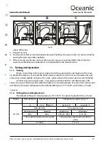
xii. Fill the rocks loosely around the elements, try to use the larger rocks between the elements
and use the smaller ones for the top.
xiii. To prolong the life of your sauna you can use a heatproof board behind and above the
heater to prevent charring, for commercial cases this should be more seriously considered.
10.3. Wiring of sauna heater and components
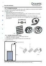
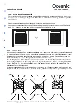
Remove the cover panel and connect power supply wire and control cable through the wire
anchorage to the Terminal as per fig 8 and replace the cover panel.
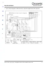
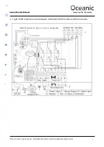
If wiring single phase, it is only the input connections into the OCSB control box L1, L2, L3 that
need to be linked (see fig2a). Do not short circuit output from the control box to sauna heater or
across the live terminals of on the heater.
The correct size heat proof cable is required to the heater from the control box. This is not
supplied as standard but can be bought at the required length from Oceanic Saunas Ltd or a
local electrical wholesaler.
Sauna heater, Control box ,light ,fan and temperature sensor connection drawing.
Optional Door interlock (commercial use), install the switch following the manufacturers
instructions and connect the wires back to the control box as shown below.
Fig 8
OCSB Keypad
5V DC
Temperature
Sensor
Lighting
Door interlock
(optional)
2 core cable
(not supplied)
Apollo Heater
Mains Power
240 1N~ / 400V 3N~
Isolator Switch
OCSB/LB Contol Box
5 core heat proof silicon cable (not supplied)
Heat proof silicon cable must be used
between the controller and heater unit.
6 pin control cable (supplied)
4 core control cable (supplied)
3 core mains cable (not supplied)
If using single phase link
across L1, L2, L3 with copper
bridges or pieces of cut wire
see Fig2a


