background image

18 

CONTROLLER PROGRAMMING MENU 


1)  

Make sure the unit has power . 


2)  

Press the power button 

“OFF”. 


3)  

Press the following buttons in sequence 

S-U-D-S”  


(

S

elect—

U

p arrow — 

D

own arrow — 

S

elect) 


4)  

The display will begin flashing P1 and a number.


If there is no display, repeat the sequence,  

making sure the unit has power, but is turned OFF. 


5)  

To adjust any program feature, press the 

ARROW UP

▲ or 

ARROW DOWN 

▼ button 

until the desired value is displayed. 

6)  

Use the “

MODE” 

button to scroll through the programmable settings P1 through P16. 

7)  

If no buttons are pressed, the display will then return to the “

OFF

” position after about 

50 seconds. 


PROGRAM SETTINGS 

P1—High Fan Speed Limit Setting. 56 - 85 
P2—Low Fan Speed Limit Setting, 30 - 55 
P4—Temperature Sensor Calibration, +/- 10° 
P10— Temperature Display, °F or °C 
P13—Supply Fan Operation, Cycling or Continuous 
P15—Fan Motor Type Setting, PSC or Shaded Pole 


P1, P2 

- To adjust fan speed settings, 

P1

 represents the high fan speed parameter, while 

P2 represents the low fan speed parameter.  When using nozzle kits, discharge duct 
adapters and evaporator plenums, setting P1 to 85 will help to avoid freeze ups.   


P4

 - Adjust the 

P4

 setting to match the actual INSIDE room temperature, if needed. 


P10

 - Use this parameter to display temperatures in the desired units. 


P13

 - To cycle the evaporator fan with the compressor, access code 

P-13

. Press the up 

or down button to switch to “

CYC

”, which means cycle the fan with the compressor. The 

factory default setting is “

CON

”, which means continuous fan operation. 


P15

 - Fan Motors are PSC type, 

SC

 - should be selected.


8)  

Press 

POWER 

   — you should see an alphanumeric code. 


Press 

POWER

 and the unit will start at the new settings 

FAN SPEED

The operator can select between 

AUTO or MANUAL 

fan speed control.  

Pressing the 

FAN SPEED 

button, will switch speed from 

AUTO to MANUAL

.  In 

MANUAL 

mode, pressing the 

FAN SPEED 

button will change fan speed from low to high.  In 

AUTO


mode,  the fan speed is controlled automatically.  In cooling mode, the controller  
automatically adjusts the fan speed to high, and as the inside temperature approaches 
the set point, the fan speed will reduce.   
 

TEMP SELECT

— 

Allows the operator to view the controller temperatures 

INSIDE

 = return air temperature, 

DISCHARGE 

= supply air temperature,  

SET POINT 

can be seen and adjusted, by pressing ▲ or▼. 

Summary of Contents for CAC series

Page 1: ...ENGINEERING INSTALLATION AND SERVICE MANUAL CAC series Portable Air Cooled Spot Cooler Form EISM CAC 030115 Rev 1 ...

Page 2: ...ails for the installation and operation of the OceanAire CAC spot cooler It is recommended to read and fully understand the instructions outlined within this manual before operating the unit As with all commercial air conditioning equipment it is recommended to have the CAC sized and installed by a licensed specifying engineer and contractor in accordance with all local and state codes The length ...

Page 3: ...elf contained unit with the entire system evaporator and condenser blower assemblies electrical and refrigeration components neatly arranged in a black polyester powder coated metal cabinet When connected to the proper source of electrical power the unit is controlled by a solid state electronic controller with numerous options of temperature and airflow controls that will provide the desired leve...

Page 4: ...GAL EVAP CFM HIGH 400 CFM EVAP CFM LOW 320 CFM EVAP MOTOR AMPS 1 7 A EVAP MOTOR WATTS 130 W CONDENSER BLOWER CENTRIFUGAL COND CFM 490 CFM COND MOTOR AMPS 1 4 A COND MOTOR WATTS 150 W POWER CORD 14 3 PLUG TYPE 5 15 P CORD LENGTH 10 FT LCDI ATTACHED CONDENSATE RESERVOIR REMOVABLE TANK CAPACITY 2 GALLON REFRIGERANT R 410A CHARGE 18 OZ HEIGHT WITH CASTERS 24 in HEIGHT WITHOUT CASTERS 20 in WIDTH 17 1 ...

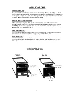
Page 5: ...ired the fan speed can be set to MANUAL mode and the evaporator blower will run continuously at one of six levels of fan speed CONDENSATE RESERVOIR TANK The CAC unit comes equipped with a Reservoir Tank for handling the condensate generated during the cooling process When the tank is full the default condition CON will be displayed The tank can be easily removed from the unit and emptied as needed...

Page 6: ...ed as a room air conditioner to cool an enclosed space Using the condenser return air panel CCP 8 and ceiling discharge kit CK 8 the CAC can operate as a room air conditioner with the condenser air isolated form the conditioned space CEILING MOUNT The CAC can be secured above a space or be installed above a drop ceiling allowing the unit to cool a room area without taking up any valuable floor spa...

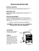
Page 7: ... GROUNDING TYPE CONNECTOR LOAD FITTING ELECTRICAL CONFIGURATION PORTABLE CONFIGURATION The CAC is equipped with a 10 foot power cord for ease of movement and portability The cord is to be plugged into a 15 Amp receptacle A dedicated circuit is required PERMANENT INSTALLATION The CAC can be installed in a permanent configuration as the control box is suitable for field wiring The unit can be hung f...

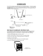
Page 8: ...ED CONDENSATE TANK TANK SPOUT EMPTYING THE CONDENSATE RESERVOIR TANK In the COOL Mode condensate will collect in the condensate tank When the tank is full the Deluxe Controller will shut down the compressor and the fault CON will be displayed along with the room temperature To empty the tank do the following 1 Press the POWER button to turn the unit off 2 Remove the tank from the lower front of th...

Page 9: ...voltage and amperage requirements For proper NEMA receptacles refer to Electrical service plug configuration When using extension cords use the proper gauge cord and check cord voltage to the unit TIME DELAY FUSES CIRCUIT BREAKERS ARE RECOMMENDED WARNING OPERATING THE UNIT ON IMPROPER VOLTAGE WILL VOID THE WARRANTY ACCESSORIES Verify that all accessories are correct for the model and are installed...

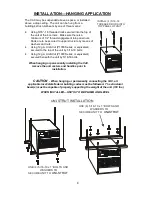
Page 10: ...unit can be hung from a building s structural beam by one of three means Using 5 16 18 threaded rods secured into the top of the unit at the 4 corners Make sure there is a minimum of 1 2 thread engagement into panel nuts Rods are to be secured to upper structure by means of washers and nuts Using 12 ga Uni Strut P1000 Series or equivalent secured to the top of the unit by 5 16 18 bolts Using 12 ga...

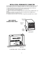
Page 11: ...he power cord from the ground lug and terminal strip 3 Remove the power cord and the strain relief 4 Install 1 2 conduit and a UL recognized bushing through the 7 8 DIA CONDUIT PORT and secure 5 Three 3 conductors a minimum of 14 AWG are required for LINE COMMON and GROUND can then be connected to the unit 6 A dedicated electrical circuit 115 VAC 60HZ Single Phase rated 15 amps is needed LCDI POWE...

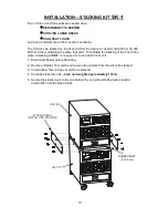
Page 12: ...e stacking of the Cool Cube units a stacking kit SK 1 is required for each additional unit 1 Disconnect Power before Servicing 2 Remove Handles from units and remove the casters from the unit to be stacked 3 Install rubber feet on base of unit to be stacked 4 Carefully stack the units each unit weights approximately 130 lb 5 Secure the stacked unit to the one below it by using the stacking rails p...

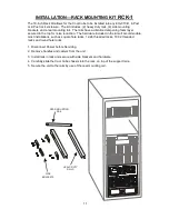
Page 13: ...ise reduction The hardware included in the kit will accommodate most installations such as square hole racks 12 24 threaded racks 10 32 threaded racks and round hole racks 1 Disconnect Power before Servicing 2 Remove handles and casters from the unit 3 Install rails in rack and secure with side brackets and hardware 4 Carefully slide the Cool Cube chassis into the rack on top of the support rails ...

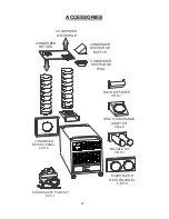
Page 14: ...UMP KIT CPC 1 CONDENSER RETURN PANEL CCP 8 NOZZLE KIT CNK 1 EVAPORATOR RETURN PANEL CEP 6 CONDENSER DISCHARGE CONDENSER RETURN 8 INCH DISCHARGE ADAPTER CDA 8 CONDENSER DISCHARGE BAFFLE CONDENSER DISCHARGE RING RACK DIFFUSER CRD 1 ...

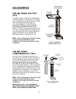
Page 15: ...d ceiling panel by use of the CVK 8 conversion kit The kit contains the parts necessary to install a second 8 Inch duct flange and a condenser discharge baffle onto the CK 8 ceiling panel This allows for ducting of condenser air to and from the drop ceiling plenum The kit contains an 8 inch duct flange and a discharge air baffle that can be installed onto the ceiling panel as shown along with an 8...

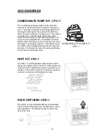
Page 16: ...f when the pump is not working properly The default condi tion CON will be displayed along with the room tem perature Kit includes the pump mounting hardware and 20 feet of condensate hose FEET KIT CFK 1 The CFK 1 is a field installed rubber feet kit that re places the casters used on the CAC allowing the unit to be mounted in applications where movement is not required The feet are made of oil re...

Page 17: ...ugh the rack to remove the hot air from the area of the equipment CNK 1 for model CAC with 2 4 inch diameter noz zles with an approximate compressed length of 15 inches The approximate extended length is 21 inches DISCHARGE ADAPTER CDA 8 A discharge adapter is available for installations where it is required to duct air away from the unit The discharge adapter easily attaches to the evaporator and...

Page 18: ...8 A condenser return air plenum is available for installations where it is required to duct air to the inlet of the condenser The plenum easily attaches to the unit and provides a collar for connecting 8 inch flexible ducting The CCP 8 has space for a 12 x 20 filter NOTE When installing the condenser return air plenum with additional duct hardware allow for a mini mum separation distance at 2 feet...

Page 19: ...will operate in cooling mode only MOISTURE CONTROL The system operates in the cooling mode to reduce humidity within the conditioned space Every 4 hours the fan is started circulating the air and the air temperature is recorded by the controller The cooling cycle is started for one hour or until the room temperature drops 2 which ever comes first This cycle repeats every four hours DELUXE ELECTRON...

Page 20: ...pters and evaporator plenums setting P1 to 85 will help to avoid freeze ups P4 Adjust the P4 setting to match the actual INSIDE room temperature if needed P10 Use this parameter to display temperatures in the desired units P13 To cycle the evaporator fan with the compressor access code P 13 Press the up or down button to switch to CYC which means cycle the fan with the compressor The factory defau...

Page 21: ...stricted condenser air flow Correct problem and re set unit at HP RESET TO CHECK THE NUMBER OF HOURS ON THE UNIT 1 Disconnect unit power and reconnect unit power 2 When 888 appears in display push and release the arrow down button 3 The first set of numbers displayed reads thousands of hours 02 2000 04 4000 hours 00 means less than 1000 hours 4 The second set of numbers read hours directly 58 58 h...

Page 22: ...DENSER FAN DO NOT START Note there is a time delay for the compressor CAUSE SET POINT setting may be too high for cooling REMEDY Make sure set point is adjusted accordingly You should see a red dot to the right of the temperature display indicating compressor ON CAUSE Loose Display Cable REMEDY Examine the control unit for loose wires Tighten any loose connections CAUSE Condition Alarm CON REMEDY ...

Page 23: ...play cable and remove display Install new display and secure Plug in display cable C POWER MODULE To remove the power module disconnect wires one at a time and re attach each wire while holding replacement module in other hand Once all wires have been reconnected in accordance with the wiring diagram install new power module D CONDENSATE PUMP ON UNITS WITH CONDENSATE PUMP KITS INSTALLED 1 Remove s...

Page 24: ... in a dishwasher or soaking them in a solution of warm water and detergent for 10 minutes Then rinsing them clean with hot water and shaking excess moisture from filter CONDENSATE PUMP Ordered as an accessory or field installed When servicing pump follow these steps 1 Make certain that the unit is disconnected from the power source before attempting to service or remove any component 2 Be sure the...

Page 25: ...ooled Spot Cooler SUCTION LINE DISCHARGE LINE FILTER DRIER ACCESS VALVES COMPRESSOR EVAPORATOR BLOWER CONDENSER COIL EVAPOTATOR COIL CAPILLARY TUBES HP RESET AIR AIR CONDENSER BLOWER REFRIGERANT FLOW PIPING SCHEMATIC EVAPORATOR ...

Page 26: ... PHASE POWER MODULE CONDENSATE TANK FULL SWITCH NC NO COM OPTIONAL CONDENSATE PUMP 2DPC 1 115V INSTALL SAFETY SWITCH IN LOW VOLTAGE LOOP REPLACING TANK FULL SWITCH O A CEAN IRE CAC1211 WIRING DIAGRAM WHEN FIELD WIRING USE COPPER CONDUCTORS ONLY DISCHARGE ...

Page 27: ...ritten instructions or has been altered or modified in any way b Product that has been subjected to any abnormal power conditions such as loss of power power surges voltage irregularities such as brown outs or phase loss on three phase equipment c any expenses including labor or material incurred during removal or reinstallation of the Product d any workmanship of the installer of the Product This...

Page 28: ...ALLED For Technical Support or to locate a distributor for service parts contact OceanAire at 847 583 0311 or 1 866 GETAIRE 438 2473 Please indicate the Model Number and Serial Number of the unit to assure proper information and service parts TECH NOTES Form EISM CAC 030115 Rev 1 ...

Reviews: