background image

46

SECTION 4: USING THE OSD MENUS
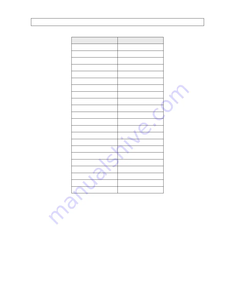
Parameters

Default Value

Focus

HAF

Zoom limit

Max Optical Zoom

Zoom speed

High

Slow shutter

Off

IR cut filter

Day

D/N level

Mid

BLC

Off

AE mode

Auto

Exposure compensation

7

White balance

Auto

Auto-flip

On

Proportional pan

On

Park time

5 seconds

Park act

None

Scan speed

28

Image freeze

Off

Limit stops

Off

Time show

Off

Zone show

On

Address show

Off

Error rate show

Off

Zoom/PT/Preset show

Off

4.10.3  Restoring camera default settings

Camera settings include the image parameters, lens settings and display settings. To restore the default settings in the camera: 

1. 

Open the menu: 

MAIN MENUS 

g

 RESTORE CAMERA

2. 

Click 

IRIS+

 to restore the camera settings to the default value; or click 

IRIS-

 to exit.

4.10.4  Rebooting the camera

Open the 

MAIN MENUS 

g

 REBOOT DOME

 menu, then click 

IRIS+

 to reboot the camera remotely.

Summary of Contents for BLK-PTZ36XIR

Page 1: ...6x Zoom Outdoor PTZ Camera User Manual Products BLK PTZ36XIR Please read this manual before using your camera and always follow the instructions for safety and proper use Save this manual for future r...

Page 2: ...04 108 EC LEGAL NOTICE Observint Technologies Observint products are designed to meet safety and performance standards with the use of specific Observint authorized accessories Observint disclaims lia...

Page 3: ...lycordisthemaindisconnectdeviceto AC power Thesocketoutlet mustbe installedneartheequipmentandmustbereadilyaccessible InstallationandMaintenance Donotconnect disconnectanycablestoorperforminstallation...

Page 4: ...y inserted into the power socket When the product is installed on a wall or ceiling it must be securely attached If the camera emits smoke odors or noise power it off immediately and unplug the power...

Page 5: ...e sure the place have enough space to install the camera and its accessories Check the intensity of conformation at the installation location Please make sure that the ceilings or walls are strong eno...

Page 6: ...tion 20 4 2 1 Checking System Information 20 4 2 2 Configuring system parameters 20 4 2 3 System time configuration 23 4 2 4 Display the PTZ movements system time fan heat etc 23 4 2 5 IR parameter co...

Page 7: ...7 Configuring Patterns 38 4 7 1 TASK 1 Set a pattern 38 4 7 2 TASK 2 Preview a pattern 39 4 7 3 TASK 3 Call the defined pattern 39 4 7 4 TASK 4 Delete patterns 39 4 8 ConfiguringTimeTasks 40 4 8 1 TA...

Page 8: ...viii...

Page 9: ...has an extreme operating temperature range of 22 F 149 F that is ideal for capturing video in cold climates and an IP66 weather rated enclosure to withstand a variety of elements and weather conditio...

Page 10: ...y move to the defined position The user can add modify delete and call each preset Label Display The on screen label of the preset title PT display zoom and time can be displayed on the monitor Auto F...

Page 11: ...re in challenging lighting environments such as hallways and doorways so the entire image of the subject in the foreground is properly exposed when there is a bright light source behind the subject Wi...

Page 12: ...an random scan frame scan panorama scan day night mode or none Park Action This feature allows the dome to start a predefined action automatically after a period of inactivity 1 2 Accessories The foll...

Page 13: ...5 36x PTZ IR Outdoor Camera User Manual SECTION 1 INTRODUCTION BLK PTZCL Ceiling Mount Bracket The Ceiling Mount Bracket is suitable for outdoor ceiling mounting 3 52 dia 0 39 dia 4 2 24 4 57 dia...

Page 14: ...6 SECTION 1 INTRODUCTION BLK PTZWB Wall Mount Bracket The Wall Mount Bracket is suitable for indoor and outdoor wall mounting 0 33 dia 4 G 1 5 6 30 7 64 2 95 3 82 12 2...

Page 15: ...ser Manual SECTION 1 INTRODUCTION BLK PTZPM Pole Mount PTZ Bracket The Pole Mount Bracket is suitable for outdoor pole mounting The straps can attach to a 2 64 5 00 diameter pole 2 68 2 68 7 64 7 64 5...

Page 16: ...8 SECTION 1 INTRODUCTION BLK PTZCM Corner Mount PTZ Bracket 7 64 6 96 G 1 5 16 52...

Page 17: ...VR or DVS See SECTION 4 Using the OSD Menus on page 18 for more information NOTE Ifyouare installingseveralRS 485networkdevicesatthesametime manuallysettingtheDIPswitchesforaddressand baudrate willhel...

Page 18: ...OFF OFF OFF 1 ON OFF OFF OFF OFF OFF OFF OFF 2 OFF ON OFF OFF OFF OFF OFF OFF 3 ON ON OFF OFF OFF OFF OFF OFF 4 OFF OFF ON OFF OFF OFF OFF OFF 5 ON OFF ON OFF OFF OFF OFF OFF 6 OFF ON ON OFF OFF OFF O...

Page 19: ...mera wall mount bracket to the mounting surface The fasteners must fit the wall mount bracket and should support at least eight times the weight of the camera and mounting bracket b Position the wall...

Page 20: ...ch supplied to hold the two units together Safety rope Lock screw 2 Drop cable Securethecameratothebracket 3 Route the camera drop cables through the hole for them drilled in the mounting surface 4 Us...

Page 21: ...for video 24 Vac power and ground and RS 485 between the remote control device and power source and your camera Do not apply power to the 24 Vac cables before connecting them to your camera Remote con...

Page 22: ...video output cables to your network extension cables Connect the other end of these cables to a remote control device such as a DVR 5 When power is applied to the camera a system information display...

Page 23: ...ion TYPE The model of the camera SN The serial number of the camera ADDRESS The default communication address of the camera COM FORMAT The communication settings of the RS 485 interface baud rate 4 di...

Page 24: ...rough a control device such as a DVS These presets are fixed and cannot be edited To call the system defined presets remotely you can choose the preset number from the list in the PTZ control panel Fo...

Page 25: ...71 Record Pattern 2 72 Record Pattern 3 3 3 On Screen Displays The camera supports following on screen displays Zoom Identifies the amount of magnification The format is ZXXX where XXX is the zoom amo...

Page 26: ...u include Enter the menu by pressing buttons PTZ g REC g 9 g 5 on the front panel of the DVR Enter the menu by pressing buttons CALL g 9 g 5 g ENTER on the keyboard Enter the menu via the IE browser o...

Page 27: ...Click IRIS to return to the previous menu or move the cursor to EXIT the menu and then click IRIS to exit the menu Page up page down There is no RETURN or NEXT menu items for turning a page up or dow...

Page 28: ...m information shown after camera power up To open the system information display menu go to MAIN MENUS g SYS INFO SystemInformation NOTE TheSYSINFOdisplayispresentedforInformationonly Itcannotbeedited...

Page 29: ...If the SOFT ADDR ACTIVE is set as OFF the hard address set by the DIP switch is the valid address of the camera TASK2 Setthebroadcastaddressofthecamera When the BROADCAST ADDRESS is set to ON the con...

Page 30: ...TER For IR Parameter settings setup see 4 2 5 IR parameter configuration on page 24 Fan parameter configuration You can set the FAN CONTROL to TEMP ON or OFF EIS Electronic Image Stabilization configu...

Page 31: ...he left or right direction buttons to position the cursor on the specific item year month day or hour minute second of which you want to change the value 3 Click the up or down direction buttons to in...

Page 32: ...resetfinishes Display the viewing direction The camera displays a viewing direction code when you manually rotate the camera Codes are shown in the table below Display N NE E SE S SW W NW Indication N...

Page 33: ...zooming rate is larger than the reference zoom it will switch to the far distance IR LED when it s smaller than the reference zoom it will switch to the near medium distance IR LED LED CONTROL LED con...

Page 34: ...et the camera parameters including focus shutter speed iris etc Configuring image parameters for the camera includes several tasks see below To open the camera parameters settings menu go to MAIN MENU...

Page 35: ...red limit of the zoom amount Zoom amount optical zoom digital zoom If you set the zoom limit to the minimum value 22 the digital zoom is disabled and the optical zoom will be at the maximum value if y...

Page 36: ...es of the picture to enhance the picture details You can set the SHARPNESS level from 0 to 15 4 3 5 Task 5 Configure the BLC and WDR There are two parameters available for BLC back light compensation...

Page 37: ...the slow shutter function for low lighting circumstances a Shutter speed If you set the SHUTTER value larger the shutter speed is faster The value indicates the inverse of the shutter speed 1 value se...

Page 38: ...is option can produce a clearer and higher quality image in the low luminance environment Saturation Saturation indicates the brightness of a color The higher the saturation the brighter the color is...

Page 39: ...buttons to select a mask number for configuration c Click IRIS again to confirm your selection 3 Configure the position and size of the privacy mask a Move the cursor to SET BLANK and click IRIS butto...

Page 40: ...TE Thetiltrangeforconfiguringtheprivacymasks is from0 to70 4 Enable or disable the privacy mask function Open the BLANK STATUS submenu then click the up and down direction buttons to set it ON or OFF...

Page 41: ...me no park actions is performed when either of these conditions exist In the process of performing dome actions by calling special presets In the process of performing external alarm linked actions Im...

Page 42: ...he range of the elevation angle is 0 90 by default It changes to 2 90 when the ELEVATION SET is enabled 4 5 Configuring Presets A preset is a predefined direction For the defined preset you can click...

Page 43: ...nsettingsarerestrictedbylimitstops iftheyaredefined 4 5 2 TASK 3 Call the presets a Through a web browser connected to an encoder select the preset number from the drop down preset list b Click the ar...

Page 44: ...IRIS to open edit mode b Click the up and down direction buttons to select the number of the patrol which is to be configured c Click IRIS again to confirm and exit edit mode of this column Patrolcon...

Page 45: ...trol e Press IRIS to save the current settings or press IRIS to cancel and return to the previous menu 4 6 2 TASK 2 Preview the patrol To review a patrol move the cursor to PREVIEW then click IRIS to...

Page 46: ...g and preset movements that can be recalled by a command or automatically performed by a configured function alarm park time task and power up 4 7 1 TASK 1 Set a pattern You can configure up to 4 patt...

Page 47: ...rizedsimultaneously 4 7 2 TASK 2 Preview a pattern To preview a pattern open the PREVIEW menu to see the current pattern 4 7 3 TASK 3 Call the defined pattern You can select the corresponding preset n...

Page 48: ...TASK submenu Go to MAIN MENUS g DOME SETTINGS g TIME TASK TimeTaskconfigurationmenu 2 Choose the task number a Move the cursor to TASK NUM and click IRIS to enter edit mode b Click the up and down dir...

Page 49: ...ons to position the cursor to WEEK START H M and END H M c Click the up and down direction buttons to select the specific start time and end time to run the task The weekday can be set to be from Mond...

Page 50: ...zone area a Move the cursor to EDIT ZONE and click IRIS button to open the submenu b When you see SETLEFTLIMIT on the screen click the direction buttons to set the left limit stop c Follow the prompt...

Page 51: ...NGS ClearSettingsmenu 2 Click IRIS on each submenu such as CLEAR ALL PATTERNS 3 Click IRIS again to confirm and close the menu 4 9 3 Using the DIAGNOSTICS display The DIAGNOSTICS display shows the sel...

Page 52: ...imes of abnormal reboot PAN LOST The occurrence times of panning loss TILT LOST The occurrence times of tilting loss CAMERA LOST The occurrence times of communication loss Panning loss and tilting los...

Page 53: ...ING submenu and switch the status to ON then click IRIS to save the setting 4 10 2 Restoring default dome settings You can reset all dome settings to factory default parameters as shown in the table b...

Page 54: ...Off Limit stops Off Time show Off Zone show On Address show Off Error rate show Off Zoom PT Preset show Off 4 10 3 Restoring camera default settings Camera settings include the image parameters lens s...

Page 55: ...On Off Auto Shutter Time 1 1 10 000 s Day Night IR Cut Filter Digital Zoom 16x Privacy Mask 8 privacy masks programmable a maximum of 8 zones can be masked simultaneously on the same video screen Focu...

Page 56: ...om ratio Input Output Monitor Output 1 0 Vp p 75 composite BNC General Menu Language English Chinese RS 485 Protocols Pelco P Pelco D self adaptive Power 24 Vac max 30 W IR LED on heater on max 24 W I...

Page 57: ...on high power lightning protection apparatus and lightning conductor are necessary The design for installation and wiring with lightning protection and grounding should be combined with the lightning...

Page 58: ...sion with 24AWG wire Baud rate Maximum distance 2400 bps 5900 ft 1800 m 4800 bps 3900 ft 1200 m 9600 bps 2600 ft 800 m The transmission distance is decreased for thinner cable when the wire is exposed...

Page 59: ...signal reflection uncontrollable or self running cameras and anti jamming inability with devices that are far away In the star shaped connection the termination resistors are usually placed in the tw...

Page 60: ...ress and baud rate to match in the controller and the camera RS 485 are connected incorrectly Correct the RS 485 wiring connections Wiring is disconnected Fastening the wire RS 485 wire is broken Chan...

Page 61: ...required is 0 8000 mm Table 7 Table of wire gauge standards Distance ft m Wire Gauge mm Power VA 0 8000 1 000 1 250 2 000 10 283 86 451 137 716 218 1811 551 20 141 42 225 68 358 109 905 275 30 94 28 1...

Page 62: ...ANCE Table 8 Wire Gauge Standards Bare Wire Gauge mm American Wire Gauge AWG Cross sectional Area of Bare Wire mm2 0 750 21 0 4417 0 800 20 0 5027 0 900 19 0 6362 1 000 18 0 7854 1 250 16 1 2266 1 500...

Reviews: