background image


Figure 5‐15


5.3.2


Disabling


URL


Filtering


To


disable


URL


Filtering,


perform


the


following


steps:


1.


Choose


Security

>

URL


Filtering

.


2.


Set


URL


Filtering


to


Disable

.


3.


Click


Submit

.


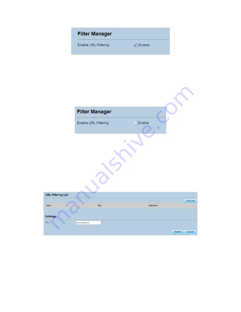
As


shown


in


Figure


5

16.


Figure 5‐16


5.3.3


Adding


URL


Filtering


list


To


add


a


URL


filtering


list,


perform


the


following


steps:


1.


Choose


Security

>

URL


Filtering

.


2.


Click


Add


list

.


3.


Set


URL

.


4.


Click


Submit

.


As


shown


in


Figure


5

17.


Figure 5‐17


5.3.4


Modify


URL


Filtering


list


To


modify


a


URL


filtering


rule,


perform


the


following


steps:


1.


Choose


Security

>

URL


Filtering

.


2.


Choose


the


rule


to


be


modified,


and


click


Edit

.


Summary of Contents for LTE CPE SQI4N4

Page 1: ...LTE CPE SQI4N4 Quick Start Guide FCC ID 2AI24QCI4NU FCC ID 2AI24SQO14 Issue 01 Date 2016 08...

Page 2: ...he SQO14 to the QCI4NU 8 5 5 Connect the QCI4NU 8 5 6 Mount the SQO14 9 5 6 1 Pole mounting 9 6 Connect to the Internet 11 7 Wireless 13 7 1 Turn the Wireless On or off 13 8 Troubleshooting 14 8 1 Pow...

Page 3: ...oo Outd e Pane NU Rear Pane NU Front Pane You N have everyth door unit and or Unit door Unit el l el Need ing required t QCI4NU d an outdoor FCC ID 2A FCC ID 2A Figure 2 1 Figure 2 2 to properly s POW...

Page 4: ...he QCI4NU Quick Start rnet It Wor nd WAN connects to t is connected U functions as Ualso serves a Guide shows rks the LTE netwo to the QCI4N s a LAN Wi as telephone s you how to Figure 4 1 ork NU Fi a...

Page 5: ...oose a mounting point that is sturdy enough to hold the SQO14 even during high winds When choosing a location to install the SQO14 remember that the SQO14 s front panel should point towards your servi...

Page 6: ...ert p 3 Align and sert a SIM QO14 is turn cable you do he cover from ve the cover ur SIM card SIM Card put the cove M Card t ned off befor this step Ot m the SQO14 r to protect it to the S e you inser...

Page 7: ...signal strength LED blinking Network Authentication CPE is authenticating Two signal strength LEDs blinking Getting IP Address CPE getting IP address from LTE network Three signal strength LEDs blink...

Page 8: ...ct th U Hardware C e you have in he SQO1 not included e CAT5e cable if you use ca es or other m ter you finish et cable O14 by take o AT5e Etherne QO14 housin he QCI4N Connections serted your S 14 to...

Page 9: ...of the QCI4NU s ETHERNET ports Step 4 Connect an analog phone to the PHONE port to use VoIP The PHONE LTE should light on 5 6 Mount the SQO14 See the installation instructions to mount the SQO14 corr...

Page 10: ...equipment Using software to enable terminal equipment aligned in the direction of the base station achieve the best effect Figure 5 4 pole typemounting B Note terminal equipment cable outlet must be...

Page 11: ...wser and enter the URL http 192 168 100 1 of indoor unit Step 2 Enter the default Username and Password Click Login Fields are case sensitive Figure 6 1 Login Screen Figure 6 1 NOTE If the login scree...

Page 12: ...f th cann re 6 2 Main S e LTE Signal not acquire LT Screen Bar Intern TE Signal To c et Icons loca check signal Figure 6 2 ated above of go to Netwo f the page ar ork Menu re grayed out t it means th...

Page 13: ...ng or repositioning of the outdoor SQO14 antenna is required Note SINR threshold parameters is 10 db 7 Wireless 7 1 Turn the Wireless On or off Step 1The WIFI is set to default as ON Step 2You can als...

Page 14: ...O Blue is off please apter MUST b blem still pers contact your SET But Button ice to default LEDs llowing defin oting roblems with D on OR e check be plugged in sists device h r local vendo tton t pre...

Page 15: ...on the QCI4NU device Step 3Wait until the LED indicator steadies Step 4 If the problem still persists device hardware component may be defective please contact our technical support 8 4 Wi Fi LED Fig...

Page 16: ...nsmitted OFF Ethernet connection is not established WAN POE Green Steady On WAN connection is normal Blinking WAN interface data being transmitted OFF WAN connection is not established If the LED is o...

Page 17: ...Indoor LTE CPE Online Help...

Page 18: ...ork Mode 11 3 1 2 MTU Setting 11 3 1 3 Setting Connect ODU 12 3 1 4 WAN Network Parameters Setting 12 3 2 Outdoor 4G Status 13 3 3 LAN Setting 14 3 3 1 Setting LAN Host Parameters 14 3 3 2 Configurati...

Page 19: ...3 URL Filtering 31 5 3 1 Enabling URL Filtering 31 5 3 2 Disabling URL Filtering 32 5 3 3 Adding URL Filtering list 32 5 3 4 Modify URL Filtering list 32 5 3 5 Deleting URL Filtering list 33 5 4 Port...

Page 20: ...8 7 1 Ping 46 8 7 2 Traceroute 47 8 8 Syslog 48 8 8 1 Local 48 8 8 2 Network 49 8 9 Account 50 8 10 Remote WEB Access 51 8 11 Logout 52 9 FAQs 52...

Page 21: ...quirements Item Requirement CPU Pentium 500 MHz or higher Memory 128 MB RAM or higher Hard disk 50 MB available space Operating system Microsoft Windows XP Windows Vista or Windows 7 Mac Mac OS X 10 5...

Page 22: ...CPE from unauthorized access change the password after your first login The CPE supports diagnostic function If you encounter problems please contact customer service for the specific using method To...

Page 23: ...ea view the version information such as Product name Software version Firmware version UBoot version As shown in Figure 2 2 Figure 2 2 2 3Viewing CPU Usage To view the CPU usage perform the following...

Page 24: ...emory usage information such as Total memory Current memory usage Max memory usage and Min memory usage As shown in Figure 2 4 Figure 2 4 2 5Viewing LAN Status To view the LAN status perform the follo...

Page 25: ...i Fi status SSID Chanel NO MAC address and WDS status As shown in Figure 2 6 Figure 2 6 2 7Viewing WAN Status To view the WAN status perform the following steps 1 Choose Overview 2 In the WAN Status a...

Page 26: ...the throughput statistics such as WAN throughput and LAN throughput As shown in Figure 2 8 Figure 2 8 2 9Viewing Device List To view the device list perform the following steps 1 Choose Overview 2 In...

Page 27: ...ttings 2 In the Network Mode area select a mode between LTE and Ethernet 3 Click Submit As shown in Figure 3 1 Figure 3 1 3 1 2 MTU Setting To set the WAN MTU size perform the following steps 1 Choose...

Page 28: ...tting Set WAN connect mode as DHCP perform the following steps 1 Choose Network Setting WAN Settings 2 In the Settings area Set connect mode as DHCP IP 3 Click Submit As shown in Figure 3 4 Figure 3 4...

Page 29: ...orm the following steps 1 Choose Network Setting Outdoor 4G Status 2 In the Outdoor 4G Status area you can also view the network information such as connect mode IMSI RSSI frequency DL UL MCS RSRP RSR...

Page 30: ...ember Make sure that IP address is unique on your network If you change the IP address of the CPE you need to access the web management page with the new IP address To change the IP address of the CPE...

Page 31: ...ur LAN or each client must be manually configured To configure DHCP settings perform the following steps 1 Choose Network Setting LAN Settings 2 Set the DHCP server to Enable 3 Set Start IP address Th...

Page 32: ...on the LAN To add an item to the setup list perform the following steps 1 Choose Network Setting LAN Settings 2 Click Add list 3 Set the MAC address and IP Address 4 Click Submit As shown in Figure 3...

Page 33: ...the WAN are directly sent to a specified IP address on the LAN before being discarded by the firewall To set DMZ perform the following steps 1 Choose Network Setting DMZ Settings 2 Set DMZ to Enable...

Page 34: ...rface from the drop down list 5 If you select LAN as the interface you need set a Gateway 6 Click Submit As shown in Figure 3 12 Figure 3 12 3 5 2 Modify Static Route To modify an access restriction r...

Page 35: ...ers 4 1 1 Setting General Parameters To configure the general Wi Fi settings perform the following steps 1 Choose Wi Fi Wi Fi Settings 2 In the General Settings area set WLAN to Enable 3 Set Mode to o...

Page 36: ...mode and passphrase You can use either the WPS button or PIN to add the wireless client To configure Wi Fi WPS settings perform the following steps 1 Choose Wi Fi WPS Settings 2 Set WPS to Enable 3 C...

Page 37: ...security level If Security is set to WPA PSK WPA2 PSK Wi Fi clients connect to the CPE in WPA PSK WPA2 PSK encryption mode 7 Set the encryption mode If Sets to Description WEP Authentication mode Sha...

Page 38: ...to the CPE To configure Wi Fi MAC control settings perform the following steps 1 Choose Wi Fi Access Management 2 In the WLAN Access List Settings area set Access Policy The access policy can be set t...

Page 39: ...i Access Management 2 Click Add 3 Set MAC address 4 Click Submit As shown in Figure 4 5 Figure 4 5 To modify an item in the Wi Fi access list perform the following steps 1 Choose Wi Fi Access Manageme...

Page 40: ...ion mode to NONE the Wi Fi clients can use NONE or WEP encryption mode If you set the WDS encryption mode to WPA WPA2 PSK the Wi Fi clients can use WPA WPA2 PSK encryption mode After WDS is enabled di...

Page 41: ...ltering This page enables you to configure the MAC address filtering rules 5 1 1 Enabling MAC Filter To enable MAC address filter perform the following steps 1 Choose Security MAC Filtering 2 Set MAC...

Page 42: ...e rules To set allow access network within the rules perform the following steps 1 Choose Security MAC Filtering 2 Set Allow access network within the rules 3 Click Submit As shown in Figure 5 3 Figur...

Page 43: ...ing 2 Click Add list 3 Set MAC address 4 Click Submit As shown in Figure 5 5 Figure 5 5 5 1 6 Modifying MAC Filtering rule To modify a MAC address rule perform the following steps 1 Choose Security MA...

Page 44: ...d by IP address This page enables you to configure the IP address filtering rules 5 2 1 Enabling IP Filtering To enable IP Filtering perform the following steps 1 Choose Security IP Filtering 2 Set IP...

Page 45: ...Filtering 2 Set Allow access network outside the rules 3 Click Submit As shown in Figure 5 10 Figure 5 10 5 2 4 Setting Deny access network outside the rules To set allow access network perform the f...

Page 46: ...nation IP Address Range box enter the destination IP address or IP address segment to be filtered 8 In the Destination port Range box enter the destination port or port segment to be filtered 9 In the...

Page 47: ...e deleted and click Delete As shown in Figure 5 14 Figure 5 14 5 3URL Filtering Data is filtered by uniform resource locator URL This page enables you to configure URL filtering rules 5 3 1 Enabling U...

Page 48: ...re 5 16 Figure 5 16 5 3 3 Adding URL Filtering list To add a URL filtering list perform the following steps 1 Choose Security URL Filtering 2 Click Add list 3 Set URL 4 Click Submit As shown in Figure...

Page 49: ...AT is enabled on the CPE only the IP address on the WAN side is open to the Internet If a computer on the LAN is enabled to provide services for the Internet for example work as an FTP server port for...

Page 50: ...k segment 7 Set Local port The port number ranges from 1 to 65535 8 Click Submit As shown in Figure 5 20 Figure 5 20 5 4 2 Modifying Port Forwarding rule To modify a port forwarding rule perform the f...

Page 51: ...urity Port Forwarding 2 Choose the item to be deleted and click Delete As shown in Figure 5 22 Figure 5 22 5 5UPnP On this page you can enable or disable the Universal Plug and Play UPnP function To e...

Page 52: ...from Protocol drop down list 4 Enter Username and Password 5 Click Submit 6 You can view the status in VPN Status area As shown in Figure 6 1 Figure 6 1 7 VOIP The CPE supports voice services based on...

Page 53: ...er 4 In the Proxy server address box enter the address of the proxy server provided by your service provider for example 192 168 1 10 5 In the Proxy server port box enter the port of the proxy server...

Page 54: ...ount provided by your service provider 4 In the Phone Number box enter the SIP Phone number provided by your service provider 5 In the Display Name box enter the display name provided by your service...

Page 55: ...8 2 The CPE is then restored to its default settings Figure 8 2 8 1 3 Backup Configuration File You can download the existing configuration file to back it up To do so 1 Choose System Maintenance 2 Cl...

Page 56: ...Upload As shown in Figure 8 4 The CPE uploads the backed up configuration file The CPE then automatically restarts Figure 8 4 8 2Version Manager This function enables you to upgrade the software versi...

Page 57: ...field 4 Click Submit 5 The software upgrade starts After the upgrade the CPE automatically restarts and runs the new software version As shown in Figure 8 6 During an upgrade do not power off the CPE...

Page 58: ...are automatically set using the TR 069 function and you do not need to set other parameters on the CPE To configure the CPE to implement the TR 069 function perform the following steps 1 Choose System...

Page 59: ...ime with the specified Network Time Protocol NTP server If you enable daylight saving time DST the CPE also adjusts the system time for DST To set the date and time perform the following steps 1 Choos...

Page 60: ...y server for time synchronization 4 From the Secondary NTP server drop down list select a server as the IP address of the secondary server for time synchronization 5 If you don t want to use other NTP...

Page 61: ...c IP address to a fixed DNS service To configure DDNS settings perform the following steps 1 Choose System DDNS 2 Set DDNS to Enable 3 In Service provider choose DynDNS org or oray com 4 Enter Domain...

Page 62: ...PE fails to access the Internet run the ping command to preliminarily identify the problem To do so 1 Choose System Diagnosis 2 In the Method area select Ping 3 Enter the domain name in the Target IP...

Page 63: ...m To do so 1 Choose System Diagnosis 2 In the Method area select Traceroute 3 Enter the domain name in the Target IP or domain field For example www google com 4 Set Maximum hops ad Timeout 5 Click Tr...

Page 64: ...ions and key running events 8 8 1 Local To set the syslog to local perform the following steps 1 Choose System Syslog 2 In the Setting area set the method to Local 3 In the Level drop down list select...

Page 65: ...display 8 8 2 Network To set the syslog to network perform the following steps 1 Choose System Syslog 2 In the Setting area set the method to Network 3 In the Level drop down list select a log level 4...

Page 66: ...o change the password perform the following steps 1 Choose System Account 2 Select the user name if you want to change the password of normal user you need to set Enable User enable 3 Enter the curren...

Page 67: ...protocol from WAN side 3 Set HTTP port If you want to change the login port you can set a new port in the box the default HTTP port is 80 4 Set HTTPS enable If you want to login the web management pag...

Page 68: ...wireless network Check that the power adapter is connected properly Check that the CPE is placed in an open area that is far away from obstructions such as concrete or wooden walls Check that the CPE...

Page 69: ...to the default settings After configuring the parameters download the configuration file to quickly restore the CPE to the desired settings...

Page 70: ...in accordance with the instructions may cause harmful interference to radio communications However there is no guarantee that interference will not occur in a particular installation If this equipmen...

Page 71: ...xposure limits set forth for an uncontrolled environment This equipment should be installed and operated with a minimum distance of 20cm between the radiator and any part of your body The antennas mus...

Reviews: