background image

MC 2000

Expandable MIDI Master Controller

108

5.5.3. Aftertouch

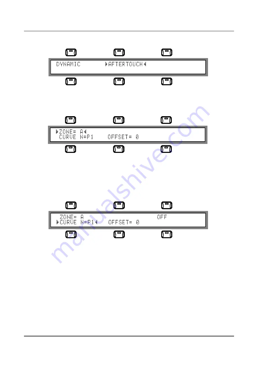
From  the  "CURVES"  submenu,  pressing  key  [F2]  (direct  access  to  the  function)  or
selecting "

AFTERTOUCH

" in  the  usual  way  will give  access  to  the page  for  setup  of  the

Aftertouch curve assigned to the zone.

This section is identical to that relating to the dynamic curves, with the only difference that
here the 32 curves relating to the Aftertouch function present in the instrument's ROM are
assigned to the zone.
Here again,  when  the  page is  accessed  the "

ZONE

"  field  will  be  selected,  and  when  the

"

CURVE  N

"  field is  selected,  the  name  of  the  selected  curve  will  appear in  the top  right-

hand corner of the display.

The OFFSET field which appears for the Aftertouch curves has exactly the same function
as the field of the same name found in the dynamic curves; i.e. it allows modification of the
sensitivity to prolonged pressure on the keyboard keys.

Once  the  setup  has  been  completed,  press  [ESC]  to  return  to  the  previous  page
("CURVES" submenu) and if required [ESC] again to return to the MAIN page of the Edit
menu.

The 32 Aftertouch curves in the MC 2000 ROM are illustrated and analyzed below:

Summary of Contents for MC 2000

Page 1: ...Manuale Operativo MASTER CONTROLLER EXPANDABLE MIDI M C 2000 Operating Manual...

Page 2: ...wl kitchen sink in a wet basement or near a swimming pool or the like This product either alone or in combination with an amplifier and headphones or speakers may be capable of producing sound levels...

Page 3: ...e mode keys 1 3 6 Rear panel elements 2 Let s switch on the MC 2000 2 1 What the instrument does at the switch on 2 2 Setting the switch on mode 2 3 Selecting the patch which will automatically appaer...

Page 4: ...iguration 7 2 1 Introduction 7 2 2 IN Status 7 2 3 MIDI Filter 7 2 4 MIDI Program Map 7 3 MIDI Bulk Dump 7 4 Edit Tables 7 4 1 Introduction 7 4 2 OUT Names 7 4 3 Program Change Tables 7 4 4 Sys Ex Tab...

Page 5: ...MC 2000 Expandable MIDI Master Controller 79 9 Supplementary messages 9 1 Malfunction messages 9 2 Error messages 9 3 Status messages 10 Annex 10 1 Reset Factory Settings procedure 10 2 Panic function...

Page 6: ...mation which presets the instrument to provide a given type of performance For example as well as the key velocity dynamic or Aftertouch response curves a patch may contain MIDI channels and relative...

Page 7: ...t is important to bear in mind that while the control associated to each wheel acts on all the active zones system control the control assigned to the Assignable Slider only acts on the zones set by t...

Page 8: ...field to which they are associated 1 3 4 The dynamic encoder the INC and DEC keys and the cursor keys Further to the right on the front panel we find the DYNAMIC ENCODER knob The Encoder is a data ent...

Page 9: ...o the chosen key can be pressed repeatedly to scroll through all the letters assigned to it The numeric pad contains the BANK key for selecting the bank in which the patch to be recalled is located Th...

Page 10: ...OUT ports 2 MIDI THRU ports and 2 MIDI IN ports all consecutively numbered The presence of 4 totally separate MIDI outputs means that data can be transmitted on 64 independent MIDI channels 16 for ea...

Page 11: ...play shows the presentation video page and information about the condition of the lithium battery fitted and whether or not the internal sound board is installed There are three types of message to in...

Page 12: ...y to the ID request the board has not been found no board installed If the MC2000 has detected a change in the configuration of the internal slot board removed of different type from the previous one...

Page 13: ...g to the batteries and the sound board which will only appear if they have top priority e g back up battery flat N B The lifetime of the lithium battery installed in the MC 2000 is estimated at 4 year...

Page 14: ...ATCH WHICH WILL AUTOMATICALLY APPEAR AT SWITCH ON You can choose the patch which will automatically appear when the instrument is switched on To do this access the POWER ON page just described in the...

Page 15: ...g the ENTER key The BANK key also operates on the same principle with cyclic selection between banks A and B When the memory bank only is selected without the patch number the current patch number wil...

Page 16: ...ttributed to the selected port which can be defined by the user see UTILITY Tables section of this menu appears in the right hand part of the display The value of the PORT field depends on whether or...

Page 17: ...ne in which the function is to take effect All zone keys relating to the zones enabled in the current patch start to flash awaiting the selection which is made by pressing the key of the chosen zone O...

Page 18: ...de are intended for the current patch the user simply presses the WRITE key again and the same patch will be saved with the new modifications If the modifications are intended for a new patch created...

Page 19: ...evices can be used to create a new memory location name Once the desired result has been obtained press the F6 function key to return to the previous page retaining the modifications made to the name...

Page 20: ...el ZONE DEFINITIONS definition of the zone Key Range Transpose and Mode OUT MESSAGES assignment of the messages belonging to the zone such as Program Change Bank Select Volume Pan pot Reverb and Choru...

Page 21: ...ection This field cannot be selected and is only visible when the PORT field is selected STATUS Selection of the activation status of the zone The possible values for the status field are ON Selected...

Page 22: ...been selected the value desired can be allocated by pressing the desired key directly on the keyboard TRANSP selection of the transposition value of the selected zone in a range between 24 and 24 semi...

Page 23: ...rds supported and some of the expanders most commonly found on the market However it will be possible to set personalized associations in 16 user tables U33 U48 in the instrument s utility section Whe...

Page 24: ...iated to the zone When the function key F6 is pressed or the field is selected using the cursor location devices followed by ENTER the display will be updated as shown below As can be seen when the PR...

Page 25: ...f the parameters listed above with the option of the OFF condition message not sent and a range of 0 127 The fields are selected and the values modified using the usual procedure As can be seen agains...

Page 26: ...dited is assigned to a recognized installed sound board the association between the control change number and the relative name is modified on the basis of the MIDI implementation of the board install...

Page 27: ...actually contain any type of bytes included in the range permitted by the MIDI protocol this allows the most expert user to create his own personalized strings which can contain not only exclusive sy...

Page 28: ...or selecting the DYNAMIC field with the usual procedure will give access to the section allowing the dynamic curves to be assigned to the zones of the current patch The display will show the followin...

Page 29: ...ge of values is from 127 to 127 note that with extreme positive values the curve tends to become flat 127 dynamic fixed at 127 while at extreme negative values it tends to become flat 0 dynamic fixed...

Page 30: ...m high dynamic values applied to the keyboard MEDIUM An absolutely straight curve also known as the standard dynamic curve meaning that the dynamics applied to the keyboard are converted into MIDI dyn...

Page 31: ...HT FEEL WEIGHT Obtained by combining the curve light and feel weight curves this curve makes it very easy to reach medium dynamic values but becomes gradually heavier in a linear trend toward the top...

Page 32: ...s of Light type shelf on the high dynamic zone MEDIUM SHELF The Medium Shelf curve has its shelf in the medium dynamic area During the performance it will be noted that medium dynamic values persist o...

Page 33: ...RSED 3 A variation on the previous Reversed curves with reduction of the MIDI dynamic values in response to minimal dynamic values applied to the keyboard Also note the different trend in the central...

Page 34: ...ere again when the page is accessed the ZONE field will be selected and when the CURVE N field is selected the name of the selected curve will appear in the top right hand corner of the display The OF...

Page 35: ...in control of the parameter associated to the Aftertouch while maintaining the chara cteristics of the Soft curve family FEEL SOFT Although still belonging to the Soft curve family the Feel type is a...

Page 36: ...r the highest level of pressure on the keyboard CUSTOMIZED 2 Another Custom type curve CUSTOMIZED 3 Another Custom Aftertouch curve giving a hard response to low intensity pressure on the keyboard bec...

Page 37: ...s of the curve stable regardless of variations in the pressure applied to the keyboard This is a Light type curve SHELF ON MID The Medium Shelf curve has its shelf in the area of medium pressure appli...

Page 38: ...0 corresponding to the maximum pressure applied to the keys TRIANGLE 2 This curve differs from the previous one in that the rising and decreasing zones are perfect mirror images of each other The max...

Page 39: ...key F2 or using the cursor location devices At this point the CC field is selected using key F4 or the cursor location devices and the Data Entry devices are used to set in it the number of a CC for t...

Page 40: ...has not already been carried out in the OUT MESSAGES page To avoid entering contradictory data it is advisable to set the default condition as OFF for all those data which might be set in other secti...

Page 41: ...ng with ENTER at this point the display will appear as shown below Note that here again the display only field in the top right hand corner shows the name of the Control Change being selected when its...

Page 42: ...y the instrument prompts the user to enter the number of the chain The second line contains in brackets the enabled functions of keys F5 and F6 the only function keys active in this video page The two...

Page 43: ...on to the fields already described the bottom line contains 3 fields lower case letters and in brackets which act as icons for the function keys below Their functions are ins INSERT STEP when key F4 c...

Page 44: ...er and name of the patch associated to it When function key F6 next is pressed the current patch will be loaded each time the key is pressed after this the step will be increased by one unit and the c...

Page 45: ...this the LED in the key will begin to flash and the display will show the following video page Press ESC to return to the previous page As can be seen the display contains 2 lines the upper line allo...

Page 46: ...the Program so the procedures are also identical they are described in section 4 Once the name is complete press function key F6 to return to the previous page destination selection and maintain the m...

Page 47: ...e are saved automatically The first video page which appears on the display as soon as this operating mode is selected using the key provided in the MODE keys group on the right of the front panel is...

Page 48: ...t recognized as specific port for the control channel IN1 IN2 STATUS when this is set on SYS the incoming messages control the functions of the Master Keyboard if this case is set on SND the messages...

Page 49: ...r to create a personalized map where he can set the order of the patches which can be recalled from a remote unit with consecutive program change numbers In other words the user can create a free asso...

Page 50: ...hes tables etc It can take a long time to dump all the data contained in the memory of the MC 2000 For this reason the instrument is also able to perform partial dumps which allow saving of just some...

Page 51: ...it contains will be irretrievably lost 3 During reception of the BULK DUMP data the MC 2000 should be in Program Mode Remember that when an active filter is set on the exclusive systems BULK DUMP rec...

Page 52: ...ange Tables Pressing the F2 function key or selecting the PRG TABLES option in the usual way from the Edit Tables page gives access to the Program Change Tables page where the user can selected each o...

Page 53: ...ous Program Changes in the table using the Encoder The name associated to each Program Change number appears in the top right hand corner of the display and can be modified in the dedicated page acces...

Page 54: ...sive systems in fact they accept any MIDI command proposed in the form of a hexadecimal code This feature allows more expert users to create not only exclusive systems but also strings of other kinds...

Page 55: ...the operation if there have been no problems the display will show the message LEARNING COMPLETE and after this all the bytes of the code just acquired will appear Otherwise the message NO DATA LEARN...

Page 56: ...SSIGN NEW EXCTABLE NAME subpage where the name is assigned using the procedure described in section 4 Once the name has been typed it is confirmed by pressing F6 done and the table can be memorized wi...

Page 57: ...e control assigned to the selected wheel appears in the top right hand corner of the display 7 5 3 Sliders Range Selecting the SLIDER RNG field or pressing F2 from the System Control video page gives...

Page 58: ...he Slider Range page illustrated in the previous point with the only difference that here the range of the 4 pedals is set instead of that of the 4 sliders so the modification procedures are identical...

Page 59: ...WN 14 PANIC Each of the two system pedals can also behave as a non system pedal ASSIGNABLE PEDAL and thus act in the specific way assigned within each patch For example if pedal 1 has been designated...

Page 60: ...ctions such as preventing access to the internal port or making incorrect associations in the Program and Control Change tables When this video page is accessed the MC 2000 displays the type of board...

Page 61: ...ard s potential to be tested without having to carry out manual programming After confirmation of loading of the dedicated programs the MC 2000 displays a warning message to point out that these new p...

Page 62: ...the display contract In this page the selection devices are deactivated because there is only one field which is thus automatically selected as soon as the video page appears The Data Entry devices c...

Page 63: ...D switch on procedure display of the logo battery status etc or is to use the SILENT procedure in which the Program mode is accessed directly To select this field press F1 or select the option using t...

Page 64: ...atically be memorized N B The last function key is only operational when the PATCH POWER ON field is selected 8 INSTALLING THE SOUND GENERATION BOARD 1 Switch off the MC 2000 and disconnect the power...

Page 65: ...the sound board see next diagram into the male connector of the MC 2000 mother board see previous diagram Remove the jumper from the connector of the board Take great care to insert the connector cor...

Page 66: ...are to be loaded If the board is not recognised a set of programs following the GENERAL MIDI mapping will be loaded The display will show If the user replies no key F6 the machine will abort the opera...

Page 67: ...Controller 141 10 The instrument will display the word Executing for a few moments and will then show the Play mode video page N B If the instrument notes that the sound board is not present points 8...

Page 68: ...noted that a UART chip does not respond to the system Since the UART chips control the serial ports of the MC 2000 i e the MIDI OUT ports after display of this message some of them might not work pro...

Page 69: ...e MIDI data at the MC 2000 input ports Check the instruments from which the data originate and the connections made PATCH NUMBER BANK ERROR The memory location of the selected patch contains data not...

Page 70: ...an only be recalled when at least two zones are active SENDING PANIC MESSAGE You have requested the PANIC function and keys simultaneously The message persists on the display until the relative messag...

Page 71: ...onstructor of the transmitter devices The message is only displayed if the Display Messages in the MIDI Common Control Channel section is set at YES Section BULK DUMP in progress During the BULK DUMP...

Page 72: ...red completed BULK DUMP IN RECEIVED This message indicates that the MC 2000 is receiving the MIDI Bulk Dump data BULK DUMP IN ABORTED The reception Bulk Dump procedure has been interrupted by the user...

Page 73: ...ceived on the MIDI IN ports the instrument reminds you that the filter is active CHAIN EMPTY You have selected a Chain which does not contain steps empty Chain so it will not be available for performa...

Page 74: ...ain has been reached IN 1 2 DEVICE DISCONNECTED The MC 2000 has detected that a device previously connected to the MIDI IN ports is not sending the Active Sensing messages device disconnected or off S...

Page 75: ...switched on To access the FACTORY SETTING procedure first switch the MC 20000 off then switch it back on keeping the WRITE key pressed The following message will appear on the display followed after a...

Page 76: ...ll the MIDI OUT ports of a series of messages intended to restore correct operation of the connected peripherals if special situations have arisen due to errors in MIDI communications with the remote...

Page 77: ...ANGE 32 O O X O 1 All CC s are assignable to sliders and or pedals PROGRAM CHANGE True 0 127 0 127 1 2 SYSTEM EXCLUSIVE O O 1 3 SYSTEM Song Pos COMMON Song Sel Tune X X X X X X SYSTEM Clock REAL TIME...

Page 78: ......

Page 79: ...ating system since this version of the manual was completed The information contained in this version of the version of the owner s manual supercedes all previous version NOTE This equipment has been...

Page 80: ...869605 e mail viscount omniway sm Internet www viscount organs com www viscount it Distribution for Italy TITAN MUSIC S A Strada Genghe di Atto 80 47031 Acquaviva Repubblica di San Marino tel 0549 99...

Reviews: