background image

6.3.4 Rename users

The “rename” command can be used to rename a user already registered into the database. To do so, simply use the command
“rename user_ID newusername.” Below is an example of the command being used.

SHELL>> rename 0 Cooper
Update was successful

Figure 49. Rename registered user

6.3.5 Manually save users into flash

Registered faces are automatically saved into flash to ensure user access after a board reset or power cycle. However, if the
autosave feature has been disabled (refer to the software developer's guide), the "save" command can be used to manually store
registered users into flash. Users are saved in the order that they were added and a success message is returned when the
command finishes running.

SHELL>> save
Saving users to flash…
User list saved

Figure 50. Manually save all registered users into Flash memory

6.4 Display configuration

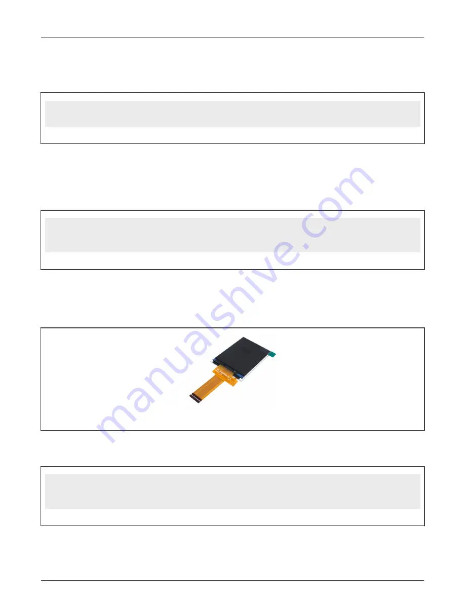
The SLN-VIZN3D-IOT kit comes pre-assembled with the Rocktech RK024HH298 VGA portrait 2.4 inch parallel TFT screen, but
the graphical interface for the Smart Lock application can also be pushed over USB to a computer screen similar to a regular USB
web camera device.

Figure 51. Rocktech RK024HH298

To activate the USB Video Class (UVC) and display the camera output with the graphical interface of the Smart Lock application
on a computer screen, type the command “display_output UVC” in the serial terminal. After issuing the command, a reset of the
board using either the “reset” command or physically power cycling the board is required for the change to take effect.

SHELL>> display_output UVC
Display output set. Reset the board for the change to take effect.
SHELL>> reset

Figure 52. Enable UVC video output command

NXP Semiconductors

Additional features

SLN-VIZN3D-IOT Kit User Guide, Rev. 0, 01 November 2021

User Guide

32 / 47

Summary of Contents for SLN-VIZN3D-IOT

Page 1: ...SLN VIZN3D IOT Kit User Guide NXP Semiconductors Document identifier SLN VIZN3D IOT UG User Guide Rev 0 01 November 2021 ...

Page 2: ...s 17 5 3 Managing users 19 5 3 1 Adding users 19 5 3 2 Modifying users 21 5 3 3 Deleting users 22 Chapter 6 Additional features 24 6 1 Low power mode 24 6 1 1 Pushbuttons 24 6 1 2 PIR sensor 25 6 1 3 Automatically enable low power mode 26 6 2 Serial command line interface 28 6 2 1 Connect to the serial command line interface 28 6 2 2 List available commands 29 6 3 Manage user database 30 6 3 1 Lis...

Page 3: ...SLN VIZN3D IOT 41 6 14 Terminate the SLN VIZN3D IOT CLI 42 Chapter 7 Troubleshooting 43 7 1 Registering a face 43 7 1 1 Adjust face proximity and position 43 7 1 2 Debug using log messages 43 Chapter 8 Document details 44 8 1 References 44 8 2 Acronyms and definitions 44 Chapter 9 Revision history 46 NXP Semiconductors Contents SLN VIZN3D IOT Kit User Guide Rev 0 01 November 2021 User Guide 3 47 ...

Page 4: ...uick inferencing and short boot times needed to deliver a great user experience TARGET APPLICATIONS Smart door locks for consumer and hospitality applications including single family homes multiple dwelling units and hotels Access control for office and industrial smart building applications 1 1 RT117F vision crossover processor overview The i MX RT117F is an Edge Ready member of the i MX RT1170 f...

Page 5: ...a module a 2 4 inch TFT display and a speaker to allow for rapid prototyping of any smart lock project with 3D face recognition capabilities These additional peripherals are shown in Figure 2 Figure 2 SLN VIZN3D IOT kit callout NXP Semiconductors Introduction SLN VIZN3D IOT Kit User Guide Rev 0 01 November 2021 User Guide 5 47 ...

Page 6: ...or non visible infrared light which can be hazardous to human eyes Products which incorporate these devices must follow the safety precautions given in IEC 60825 1 and IEC 62471 CAUTION NXP Semiconductors Introduction SLN VIZN3D IOT Kit User Guide Rev 0 01 November 2021 User Guide 6 47 ...

Page 7: ...using terminals running Android 8 or higher 2 3 Usage condition The following information is provided per Article 10 8 of the Radio Equipment Directive 2014 53 EU 1 Frequency bands in which the equipment operates 2 The maximum RF power transmitted Table 2 Bluetooth frequency and power PN RF technology Frequency range Maximum transmitted power SLN VIZN3D IOT Bluetooth 2402 2480 MHz 10 dBm EUROPEAN ...

Page 8: ...the preconfigured smart lock application Before using your kit remove the protection films on the 3D camera and the RGB camera see Figure 4 which protect the lens during transport Otherwise the depth and image capture will be wrong Figure 4 Removing camera protection films To get started take the USB C cable provided in the kit and plug the USB A end into your computer s USB port and the USB C end...

Page 9: ...kit When connected the RGB camera video appears framed with some application settings Figure 6 Boot phase completed NXP Semiconductors Getting started with SLN VIZN3D IOT SLN VIZN3D IOT Kit User Guide Rev 0 01 November 2021 User Guide 9 47 ...

Page 10: ... confirming that the registration started During the face registration process the Registering message appears in green at the top of the screen and a green bounding box appears to help align the user s face Additionally a timeout counter represented by a blue bar located at the bottom of the screen appears automatically and starts to count down To register your face look straight on to the camera...

Page 11: ...screen displays a message in red as shown in Figure 10 Figure 10 Registration failed To retry press and release the SW3 button again If you have trouble successfully registering a face try adjusting the proximity to the camera either closer or further away or move your head left right and up down so that the camera can get a better view of different angles of your face For more information see Tro...

Page 12: ...Figure 12 Manual deregistration button The speaker plays an audio message confirming that the de registration started During the face de registration process the Deregistering message appears in green at the top of the screen and a red bounding box appears to help you align your face A timeout counter represented by a blue bar starts to count down To de register your face look straight on to the c...

Page 13: ...r that was removed and the number of registered users is decremented by one Figure 14 Successful de registration Faces can also be deleted through the command line interface or the phone app described in the following sections NOTE If your face fails to de register due to the de registration being canceled or timing out the speaker plays an error message and the screen displays a message in red as...

Page 14: ... face This level of protection is crucial in applications that require security to prevent face spoofing attacks As shown in the screenshot below attempting to display a fake face to the camera results in a Fake Face UI message and audio prompt Figure 16 Printed picture 2D and mask 3D spoof attacks By requiring a user s actual face to unlock the system as opposed to a simple picture of the user s ...

Page 15: ...Figure 17 3D camera depth and IR views NXP Semiconductors Local face management SLN VIZN3D IOT Kit User Guide Rev 0 01 November 2021 User Guide 15 47 ...

Page 16: ...art_Lock_Manager apk file on your smart device by downloading it directly from your device s web browser or by transferring it from your computer to your device Before you can install it on your Android device make sure that third party apps are allowed on your device Go to Menu Settings Security and tick Unknown Sources to allow your phone to install apps from sources other than the Google Play S...

Page 17: ... reference boiler plate upon which a customized smartphone tablet companion application can be built NOTE 5 2 Managing kits To interact with your SLN VIZN3D IOT kit pair your kit with the Smart Lock Manager app This can be done from the app s main menu Press the Device Scan button to detect the VIZN3D devices that are within the Bluetooth range of your Android device The BLE feature of the SLN VIZ...

Page 18: ...re accessing your device enter a password to secure the connection between your Android device and the SLN VIZN3D IOT kit you want to access By default this password is 000000 Figure 22 Smart lock password screen When securely connected with the VIZN3D device the Android app displays a list of users currently registered in the kit s local face database Only one device can be connected and controll...

Page 19: ...k password 5 3 Managing users The Smart Lock Manager app can remotely manage the users registered to the SLN VIZN3D IOT kit using an Android device This includes adding listing and deleting users from the SLN VIZN3D IOT s local face database using 2 way synchronization This section describes each of these features 5 3 1 Adding users One of the key features of the Smart Lock Manager app is register...

Page 20: ...k the shutter icon at the bottom of the camera view as shown in Figure 26 while the box around your face is green Figure 26 Remote face capture screen The app asks you to type a name of the new face Tap the blue checkmark icon and select Register to finalize the registration Figure 27 Adding name of the new face NXP Semiconductors Remote face management SLN VIZN3D IOT Kit User Guide Rev 0 01 Novem...

Page 21: ...sing the smart lock device select the Sync option in the app to make the Android device aware of any changes to users that happened locally on the kit A sync is automatically performed when you connect to a board NOTE Figure 29 Sync option to update the face databases in the Android app and the kit 5 3 2 Modifying users The Smart Lock Manager app also enables you to modify registered users From th...

Page 22: ...hat happened locally on the kit A sync is automatically performed when you connect to a board NOTE 5 3 3 Deleting users In addition to adding and modifying registered users the Smart Lock Manager app also allows you to delete registered users as well From the list of the Smart Lock registered users select the user that you want to delete To delete the user select the Delete User option and confirm...

Page 23: ...gure 33 Triggering a local registration remotely If you locally register update or delete a face using the Smart Lock device select the Sync option in the app to make the Android device aware of any changes to users that happened locally on the kit A sync is automatically performed when you connect to a board NOTE NXP Semiconductors Remote face management SLN VIZN3D IOT Kit User Guide Rev 0 01 Nov...

Page 24: ...t Figure 34 Start low power mode SW1 long press The screen displays a message and the speaker plays an audio message to confirm that the board is entering sleep mode before the display turns off Figure 35 Entering low power mode During low power mode the RT117F MCU is set into the SNVS power state one of the lowest power modes supported by the processor and almost all onboard components Flash RAM ...

Page 25: ...SW8 is located near the display and controls the wakeup source s for the processor By default it is configured to respond to the SW0 pushbutton and the QN9090 BLE DIP switch configuration 1001 Some combinations may generate unwanted behavior refer to the Hardware Guide to identify the supported wake up configurations CAUTION Figure 37 DIP switch SW8 to select the wake up source The SLN VIZN3D IOT ...

Page 26: ... has completed to prevent the kit from falling asleep during processes that may take longer than the sleep timers allow for Additionally in the event of a registration deregistration the sleep mode timers reset after the registration de registration is complete As an example of how the automatic sleep mode process might work consider the following scenarios The SLN VIZN3D IOT is power cycled and h...

Page 27: ...e 39 Recognition timeout message Should 1 5 seconds pass without any events which disrupt low power mode s activation taking place the regular low power mode splash screen is displayed and the kit goes to sleep Figure 40 Enter Sleep Splash Screen Once asleep the board can only be awoken by the triggers mentioned in Figure 41 USB Power power cycling the kit the reset switch SW4 SW0 switch the PIR s...

Page 28: ... connect to the kit s serial based CLI identify the COM port associated with the kit and connect using the 115200 8 1 N XON XOFF serial settings shown below Figure 42 Serial connection settings After connecting to the kit s serial interface you will encounter a blank terminal screen which will echo back any characters that you type Use the help command to display a list of all the available serial...

Page 29: ...mands and their arguments Table 3 Serial command table Command Arguments Description help List all the registered commands exit Exit program closes serial terminal until reset version version oasis Get the version of the current application software Get the version of the current oasis library Table continues on the next page NXP Semiconductors Additional features SLN VIZN3D IOT Kit User Guide Rev...

Page 30: ...ir_pwm value Set IR LED power Value between 0 off and 100 white_pwm value Set White LED power Value between 0 off and 100 volume value Set Speaker volume Value between 0 off and 100 lpm lpm enable disable Set Low Power Timer Get the current Low Power Timer status ble address Get BLE advertising address get_manager get_manager id Get list of all the running managers Get HAL devices registered to a ...

Page 31: ... user name 6 3 3 Manually delete users To delete a previously registered user use the del n command followed by the user name or del i followed by the user ID to delete that specified user SHELL del n Cooper Delete was successful SHELL del i 0 Delete was successful Figure 46 Manually delete user Additionally using the del command with no arguments functions identically to the manual deregistration...

Page 32: ...y save all registered users into Flash memory 6 4 Display configuration The SLN VIZN3D IOT kit comes pre assembled with the Rocktech RK024HH298 VGA portrait 2 4 inch parallel TFT screen but the graphical interface for the Smart Lock application can also be pushed over USB to a computer screen similar to a regular USB web camera device Figure 51 Rocktech RK024HH298 To activate the USB Video Class U...

Page 33: ... for this display are available in the RT1060 EVK SDK package The VIZN3D board also features a MIPI display connector J206 to connect the Rocktech RK055HDMIPI4M HD720 landscape 5 5 inch TFT screen with capacitive touch Low level drivers for this display are available in the RT1170 EVK SDK package Figure 54 Rocktech RK043FN02H CT left and RK055HDMIPI4M right 6 5 Camera configuration The camera outp...

Page 34: ...ss use cases The SLN VIZN3D IOT kit comes pre assembled with the PUI ASE02808MR 150 R enclosed 2W Speaker with audio circuitry controlled by the RT117F MQS interface Figure 57 Speaker and audio circuitry The full list of audio messages supported by the Smart Lock application is available in the table below Table 4 List of audio messages for the Smart Lock application Voice ID Audio Message Activit...

Page 35: ...een 0 and 100 To disable audio prompts entirely simply enter the value 0 for the speaker volume SHELL volume 25 Volume set SHELL volume Current volume is 25 Figure 58 Speaker volume commands 6 7 Configure LED brightness 6 7 1 IR LED The SLN VIZN3D IOT kit embeds an IR LED controlled by an LED driver which can be used to modulate its power according to the lighting conditions The RT117F uses a PWM ...

Page 36: ...de The SLN VIZN3D IOT has been optimized for battery powered applications in part by supporting the ability to enter a low power state either manually using a pushbutton or automatically using a combination of timers and other triggers For more information regarding low power mode see Low power mode To control the Lower Power Timer enter the Serial command lpm with the argument enable or disable t...

Page 37: ...o the physical UART of the RT117F MCU accessible from the expansion header J202 located on the back of the kit The MCU UART uses 3V3 signals so make sure that your probe is compatible configured for this voltage The figure below shows how to connect the UART probe Some USB to serial adapters already include an internal 3V3 source and do not require the 3V3 connection to the VIZN3D board Check your...

Page 38: ...7 Error logs Debug Information useful for debugging the program This includes messages regarding various managers HAL devices and the latest inference results from the Oasis Lite face recognition engine Example 0 6 Debug MAIN Started 0 77 Debug LpmManager Starting 0 93 Debug LpmManager INIT lpm dev 0 0 339 Debug START lpm dev 0 0 384 Debug LpmManager started 0 0 401 Debug HAL_FlashDev_Littlefs_Ini...

Page 39: ...but generally not as important as debug messages Includes messages for enqueueing and dequeueing of camera frames and more fine grained Oasis related messages Example 504940 528 Info OASIS INVALID_FACE 504991 520 Info HAL_CameraDev_CsiOrbbecU1s_Dequeue 505005 386 Info HAL_CameraDev_CsiOrbbecU1s_Enqueue 505005 404 Info Submitting empty buffer 505005 421 Info HAL_CameraDev_CsiOrbbecU1s_Enqueue Figur...

Page 40: ... is also positioned correctly because it is facing the camera hence pose front Figure 71 On screen info for recognized face 6 10 Get BLE address Type the command ble address to easily display the Bluetooth ID from your kit This identifier will be necessary to quickly identify your kit in a crowded environment to pair it with the Android Smart Lock Manager App SHELL ble address BLE SSID VN60648E Fi...

Page 41: ... to provide to the kit For more information on Mass Storage Device drag and drop flashing see the SLN VIZN3D IOT Software Developer s Guide SHELL version App running in bankA Version 1 1 0 Figure 75 version command Alternatively the version oasis command identifies the version of the Oasis Lite library running on your kit SHELL version oasis Oasis version 1 23 0 Figure 76 version oasis command 6 1...

Page 42: ...m and terminates serial communication with the board until the next power cycle There is generally no scenario that requires use of this command SHELL exit Figure 78 Exit command NXP Semiconductors Additional features SLN VIZN3D IOT Kit User Guide Rev 0 01 November 2021 User Guide 42 47 ...

Page 43: ...r a face the face should ideally take up a majority of the bounding box be centered inside the bounding box and staring straight on at the camera To help ensure that the proper face angle is used it can be helpful to slowly move the face from left to right and up to down The 3D module of the Orbbec camera is calibrated to properly scan a face between 0 3 m and 1 0 m If the user s face is positione...

Page 44: ...de https www nxp com mcu vision3d SLN VIZN3D IOT Home Page 8 2 Acronyms and definitions Table 6 Acronyms and definitions Acronym Definition FTDI Future Technology Devices International GUI Graphic User Interface IOT Internet of Things IVT Instruction Vector Table JTAG Joint Test Action Group MCU Microcontroller Unit MEMS Micro Electro Mechanical System MSD Mass Storage Device OEM Original Equipmen...

Page 45: ...nued Acronym Definition RTOS Real Time Operating System SDK Software Development Kit UART Universal asynchronous receiver transmitter NXP Semiconductors Document details SLN VIZN3D IOT Kit User Guide Rev 0 01 November 2021 User Guide 45 47 ...

Page 46: ... substantive changes done to this document since the initial release Table 7 Revision history Revision number Date Substantive changes 0 01 November 2021 Initial release NXP Semiconductors SLN VIZN3D IOT Kit User Guide Rev 0 01 November 2021 User Guide 46 47 ...

Page 47: ...with security features that best meet rules regulations and standards of the intended application and make the ultimate design decisions regarding its products and is solely responsible for compliance with all legal regulatory and security related requirements concerning its products regardless of any information or support that may be provided by NXP NXP has a Product Security Incident Response T...

Reviews: