background image

NVIDIA Corporation

14


Frame Synchronization User’s Guide

– Version 3.0 

C

HAPTER

 2

NVIDIA Frame Synchronization

Detailed Setup Instructions 

Set Up the Hardware 

1

Daisy chain the graphics cards together using a standard CAT5 patch cable plugged 
into the external RJ45 connector.

You can connect to any of the two RJ45 connectors located on the graphics card 
bracket. 

Each connector automatically configures itself as an input or output after all the 
connections are made and one system is configured as a synchronization server (see 

“Set Up the Server” on page 15

). A flashing green LED indicates an input and a 

flashing yellow LED indicates an output. 

If there is no server assigned and connected, then both LEDs are a steady green.

WARNING!

 The voltage and signal on the frame lock ports are different from Ethernet 

signals. 

Do not connect a Frame lock port to an Ethernet card or network hub.

 Doing so 

can cause damage to the hardware.

2

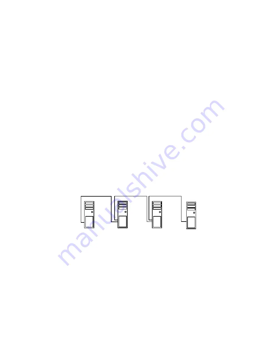
Designate one of the cards to be the server device. The remaining cards are client 
devices.

The server determines the trigger pulse for the client devices. The trigger pulse is 
derived from the V-sync of the server video. 

Figure 2.6

 shows an example of four frame locked systems. 

Figure 2.6

Example of Frame Lock Hardware Connections

Server

Client

Client

Client

Out

Out

In

Out

In

In

Summary of Contents for ForceWare Graphics Drivers Frame Synchronization

Page 1: ...ForceWare Graphics Drivers FrameSynchronization User s Guide Version 3 0 NVIDIA Corporation August 14 2006...

Page 2: ...DIA the NVIDIA logo 3DFX 3DFX INTERACTIVE the 3dfx Logo STB STB Systems and Design the STB Logo the StarBox Logo NVIDIA nForce GeForce NVIDIA Quadro NVDVD NVIDIA Personal Cinema NVIDIA Soundstorm Vant...

Page 3: ...6 Genlock Quick Start Guide 6 Detailed Setup Instructions 7 Additional Setup Instructions 10 How To Set Up Frame Lock 13 Frame Lock Quick Start Guide 13 Detailed Setup Instructions 14 Testing the Conn...

Page 4: ...N V I D I A C o r p o r a t i o n N V I D I A D r i v e r s F r a m e S y n c h r o n i z a t i o n U s e r s G u i d e V e r s i o n 3 0...

Page 5: ...his Document This document explains how to use NVIDIA Frame Lock hardware and software to enable you to create one large virtual canvas using multiple displays It contains the following main sections...

Page 6: ...ion with an NVIDIA Quadro FX 4400 NVIDIA Quadro FX 4500 or an NVIDIA Quadro FX 5500 graphics card NVIDIA Forceware Graphics Driver version 52 72 or later NVIDIA Quadro FX 4500 support requires version...

Page 7: ...graphics the display graphics must be synchronized with the video camera As another example applications presented on multiple displays must be synchronized in order to complete the illusion of a larg...

Page 8: ...processes Frame Lock Frame lock involves the use of hardware to synchronize the frames on each display in a connected system When an application is displayed across multiple monitors frame locked syst...

Page 9: ...in conjunction with an NVIDIA Quadro FX 4400 4500 or 5500 graphics card Install the NVIDIA Quadro G Sync card into any available expansion slot within six inches of the G Sync connector on the appropr...

Page 10: ...asic steps to genlocking a system Detailed instructions are provided in the section Detailed Setup Instructions on page 7 1 Set Up the Hardware Connect the external sync source to the BNC connector on...

Page 11: ...LED on the connector panel A green LED means the hardware has detected the timing signal and you can proceed to the next step An occasional red flash is OK A red LED means the hardware can t detect t...

Page 12: ...system as list arrow and then click Server 4 Click the Use house sync check box 5 If the external signal is an interlaced signal such as used to drive a 1080i60 display then click the Sync to field 1...

Page 13: ...rmation about the status indicators Using the New NVIDIA Control Panel If your driver version includes the new NVIDIA Control Panel you can set up the software as follows 1 Right click the desktop and...

Page 14: ...cting a house sync signal for the first time or after clicking Restore Defaults and then Apply Matching the External House Signal Frequency After connecting the house sync the external sync signal fre...

Page 15: ...refresh rate that you may have selected from the refresh rate list Detecting the Incoming Signal Type NVIDIA Genlock supports the following external synchronization signal types TTL 3 3 volt level Com...

Page 16: ...at the BNC connector Sync Ready Green indicates that a sync pulse is present Timing Indicates whether the timing is locked to the sync signal Green The timing is locked to the house sync Grey The tim...

Page 17: ...systems together using standard CAT5 patch cabling WARNING The voltage and signal on the frame lock ports are different from Ethernet signals Do not connect a Frame lock port to an Ethernet card or n...

Page 18: ...15 A flashing green LED indicates an input and a flashing yellow LED indicates an output If there is no server assigned and connected then both LEDs are a steady green WARNING The voltage and signal...

Page 19: ...ate to the NVIDIA graphics display properties page 2 Click the Frame Synchronization tree item from the slide out tray Figure 2 7 Frame Synchronization Page 3 Click the Treat this system as list arrow...

Page 20: ...kstation 3 From the Workstation page click Synchronize Displays 4 Under The timing server click the On this system radio button If the system has multiple displays the driver automatically selects the...

Page 21: ...e needed to display an entire frame Figure 2 9 Offset Applied to Sync Pulse 5 Click Apply to activate the changes Using the New NVIDIA Control Panel Perform the following steps for each client system...

Page 22: ...status group box displays the status of the sync signals as well as the status of the RJ45 ports The two ports are represented by connector icons See Figure 2 10 Figure 2 10 Sync and Connection Status...

Page 23: ...Red Either no signal on the frame lock connector is detected or the lock to the signal has been lost Stereo Steady green indicates that the client s stereo timing is locked to the server s stereo sig...

Page 24: ...involves a combination of genlock and frame lock In this setup a set of client systems are connected to a system that is designated as the server as described in How To Set Up Frame Lock on page 13 T...

Page 25: ...use the OpenGL extensions supported by the NVIDIA driver for accomplishing frame synchronization of applications Frame Synchronization Using the OpenGL Extensions on page 23 explains the principles b...

Page 26: ...rformed on windows Swap Groups If buffer swaps must be synchronized across several windows on a single system you can define a group that consists of the specified windows Swap Barriers If buffer swap...

Page 27: ...mentation may return zero for any of maxGroups and maxBarriers returned by QueryMaxSwapGroupsNV if swap groups or barriers are not available in that implementation or on that host Frame Counter The im...

Page 28: ...e To select the source signal upon which to base the trigger pulse call wglGenlockSourceI3D and specify either the internal sync signal or an external sync signal To query the sync source call wglGetG...

Page 29: ...to display an entire frame To determine the maximum delay value 1 Call the function wglQueryGenlockMaxSourceDelayI3D and obtain the values for maxLineDelay and maxPixelDelay 2 Calculate the maximum de...

Page 30: ...barrier There is a maximum number of barriers that can be created To determine the maximum barrier number call QueryMaxSwapGroupsNV To bind a group to a barrier call BindSwapBarrierNV and specify the...

Page 31: ...which can be queried by wglGetExtensionsStringARB This documentation covers the WGL versions of the extensions which are exported on Microsoft WindowsNT XP systems There is an equivalent Unix version...

Page 32: ...rrent genlock enable disable state Function BOOL wglEnableGenlockI3D HDC hDC Parameters In hDC Device context for the frame lock card or a window residing on the frame lock card Return Values TRUE Suc...

Page 33: ...card uSource WGL_GENLOCK_SOURCE_MULTIVIEW_I3D Select the internal sync signal as the sync source WGL_GENLOCK_SOURCE_EXTERNAL_SYNC_I3D Select the external house sync as the sync source Parameters Out...

Page 34: ...FALLING_I3D Selects the falling edge of the source WGL_GENLOCK_SOURCE_EDGE_RISING_I3D Selects the rising edge of the source WGL_GENLOCK_SOURCE_EDGE_BOTH_I3D Selects both edges of the source Parameters...

Page 35: ...te were set to a value of 2 every other sync source pulse would generate a trigger pulse uRate must be in the range of 1 6 Parameters Out Return Values TRUE Success FALSE Failure Function BOOL wglGetG...

Page 36: ...residing on the frame lock card Parameters Out uDelay The delay in pixels from the sync source trigger edge to the actual trigger pulse Return Values TRUE Success FALSE Failure Function BOOL wglQuery...

Page 37: ...V HDC hDC GLuint group Parameters In hDC Device context for the frame lock card or a window residing on the frame lock card group Swap group number to which the device context is to be assigned The va...

Page 38: ...device context is bound or assigned barrier The barrier number to which the device context is bound Return Values TRUE Success FALSE Failure In this case group and barrier are undefined Function BOOL...

Page 39: ...to zero the frame count of the swap group The call succeeds only on the master device Function BOOL ResetFrameCountNV HDC hDC Parameters In hDC Device context for the frame lock card or a window resi...

Reviews: