12
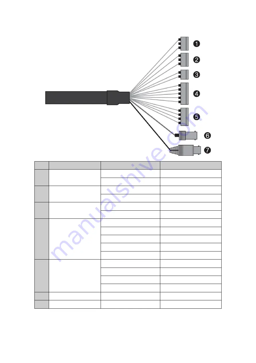
2.3 Basic Configuration of Dome Camera System
No.
Connector
Wire Color
Description
1
3-pin terminal block
RED
24VAC or 12VDC+
WHITE
24VAC or 12VDC-
2
3-pin terminal block
PINK
Heater & Fan
BROWN
Heater & Fan
3
2-pin terminal block
GREEN
RS-485+
BLUE
RS-485-
4
5-pin terminal block
GRAY
ALARM INPUT 1
VIOLET
ALARM INPUT 2
ORANGE
ALARM INPUT 3
SKY BLUE
ALARM INPUT 4
BLACK
GND
5
4-pin terminal block
YELLOW
ALARM OUTPUT 1
BLACK & WHITE
GND
SKY BLUE & BALCK
ALARM OUTPUT 2
ORANGE & BLACK
GND
6
BNC jack
BLUE
HD-TVI OUTPUT
7
BNC jack
BLACK
CVBS OUTPUT
The dome camera must be installed by qualified service personnel in accordance with all local and
federal electrical and building codes.


