NTI VOPEX-C5VA-4C1000 Installation And Operation Manual Download Page 15

NTI VOPEX SERIES SPLITTER/EXTENDER 


12


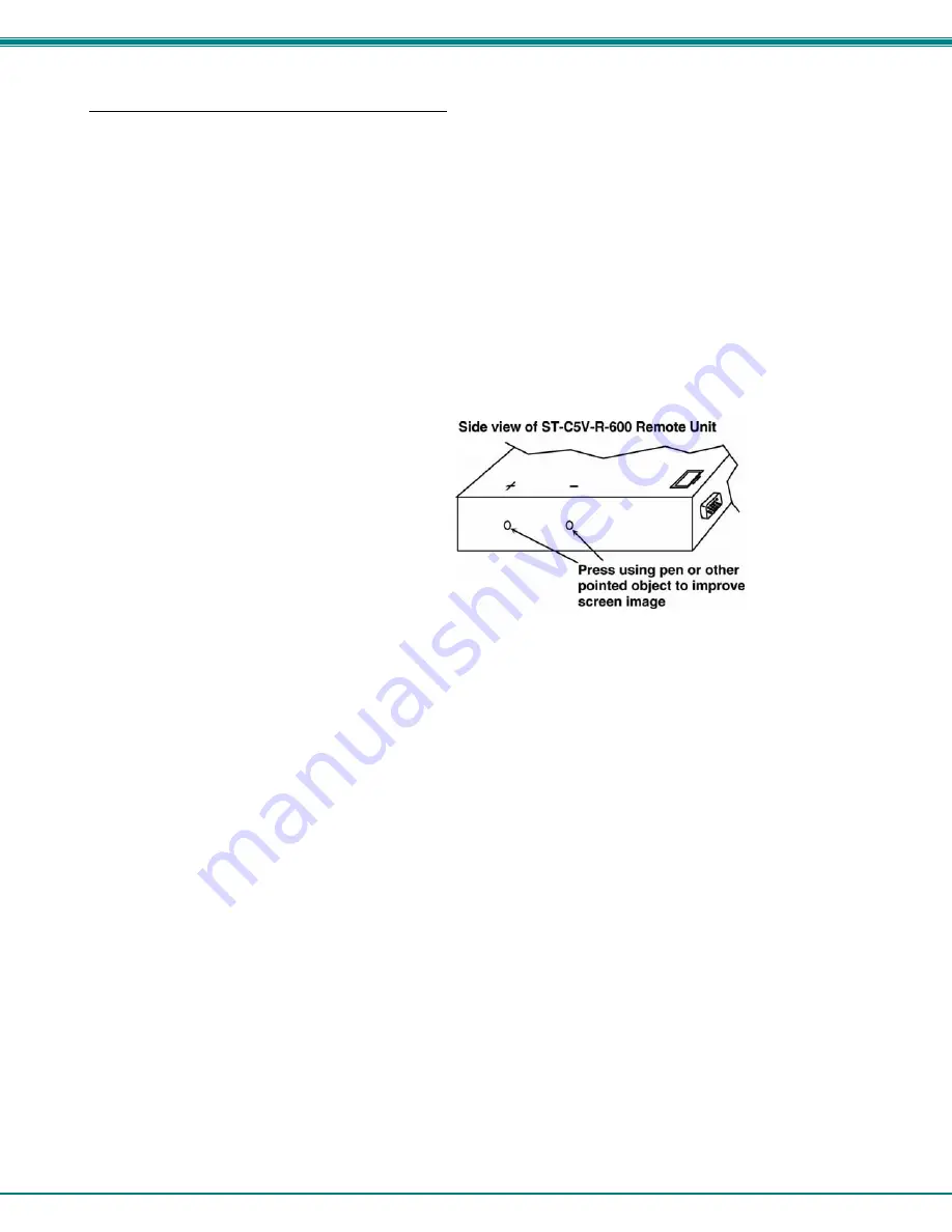
ST-C5V(X2)-R-600 Video-Only Extenders  


Video quality adjustment of the monitor connected to an ST-C5V-R-600 Remote Unit or ST-C5VX2-R-600 is performed 
manually at the Remote Unit. 


It is possible that on initial startup the image on the monitor will not be as crisp as the image normally is. This is due to the 
frequency characteristics of the CAT5 cable.    It may be necessary to press the "+"  or  "-" buttons on the Remote Unit (see 
Fig. 8) until the image is crisp and clear.   Press the "+" button if the image is not crisp and clear enough.    Press the "-" 
button if the image has been over-corrected (such that horizontal lines appear to trail or shadow at the edge of an open 
window).   A momentary press of either button will make a minor change in the image.   If either button is pressed and held, 
the changes made will be gradual and continuous.   Ultimately, the image quality should improve to a satisfactory level.   
Once the adjustment is made, it should not be necessary to change it again as the new settings are stored in memory and 
become the default settings with each startup.   
 

Note: When the cable is longer than 300 feet some colored lines can be seen at the black-to-white transitions. This 
is a normal behavior and is caused by the different twisting rates of each pair of wires in the CAT5 cable. 


Figure 8- Video quality adjustment buttons on XTENDEX Receiver 


Summary of Contents for VOPEX-C5VA-4C1000

Page 1: ...MAN186 Rev Date 12 13 2012 VOPEX C5VA xC1000 Video Audio Splitter Extender Installation and Operation Manual Receiver not included VOPEX Series...

Page 2: ...in the product design without reservation and without notification to its users WARNING Never connect a VOPEX Series VOPEX C5VA xC1000 Extender Splitter to an Ethernet card Ethernet router hub or swi...

Page 3: ...r Color Skew Adjustment 10 ST C5V R 600 Video Only Extenders 12 Technical Specifications 13 Interconnection Cable Wiring Method 14 RJ45 Connector Wiring 14 Troubleshooting 15 Warranty Information 15 T...

Page 4: ...y these parts are needed Provides an additional local access port allowing the A V source to viewed and heard locally Provides crisp and clear resolution up to 2048x1536 using NTI s 1 000 remote units...

Page 5: ...ocal user s self powered stereo speakers XTENDEX LABEL CONNECTOR LED DESCRIPTION 1 9V 1 0A 2 1x5 5mm Power Jack connection jack for 9VDC AC adapter 2 Audio Out green 3 5mm female stereo audio for conn...

Page 6: ...ded polarized and preferably surge protected 120V or 240V electrical outlet depending on the AC adapter being used must be installed close enough to the connection location of the VOPEX and XTENDEX Re...

Page 7: ...a VEXT 3 to the VGA connector on the back of the video source b Connect the female 15HD cable end of the VEXT 3 cable to the 15HD male connector marked Video on the VOPEX c Connect one 3 5mm stereo pl...

Page 8: ...CAT5 cable to any one of the Cat5x ports on the VOPEX When properly inserted the cable end should snap into place 4 Repeat step 3 for each Remote Unit to be connected to the VOPEX C5VA x Note If an R...

Page 9: ...ector can each reach the Remote Unit without putting strain on the cables 2 Connect the monitor cable to the female 15HD video connector on the Remote Unit 3 If the Remote Unit has audio support conne...

Page 10: ...female 15HD video connector on the Remote Unit 3 Connect the remote user s speakers to the 3 5mm female stereo connector on the Remote Unit see Fig 3 Figure 3 Make connections to 600 Foot XTENDEX Rem...

Page 11: ...xtension cable to the RJ45 wall outlet WARNING Never connect the XTENDEX to an Ethernet card Ethernet router hub or switch or other Ethernet RJ45 connector of an Ethernet device Damage to devices conn...

Page 12: ...to a power outlet The green LEDs on the VOPEX and the RJ45 connector of each XTENDEX Receiver should illuminate indicating that a proper power connection has been made to them See Fig 5 Figure 5 Conne...

Page 13: ...monitor may not be viewable Be sure to select a resolution setting that your installation will support For supported combinations see the chart on page 13 Video quality may need to be re adjusted if...

Page 14: ...d Flashing rapid or slow Active microphone Flash rapid remote Flash slow local press or to toggle which is active Seventh Press Dark LED OFF repeat cycle When adjusting color skew a momentary press of...

Page 15: ...ge has been over corrected such that horizontal lines appear to trail or shadow at the edge of an open window A momentary press of either button will make a minor change in the image If either button...

Page 16: ...ms Stereo Crosstalk 70 dB 1kHz Audio Maximum I O Levels 3 1Vp p Output Impedance Max 2K Ohms unbalanced Interconnect Cable CAT5 5e Solid UTP EIA TIA 568B wiring w male RJ45 connectors VOPEX C5V A 4 8C...

Page 17: ...either RJ45 connectors or M12 connectors see installation instruction for you model and must be wired according to the EIA TIA 568B industry standard Wiring is as per the tables and drawings below RJ4...

Page 18: ...d in properly and completely and reboot The picture on the monitor is black and white rather than color The video cable was not attached to the CPU when it was booted With the cables all properly conn...

Reviews: