background image

User Manual 

XTO 2.ie 


Edition A3 -  05/2021


10


Information 


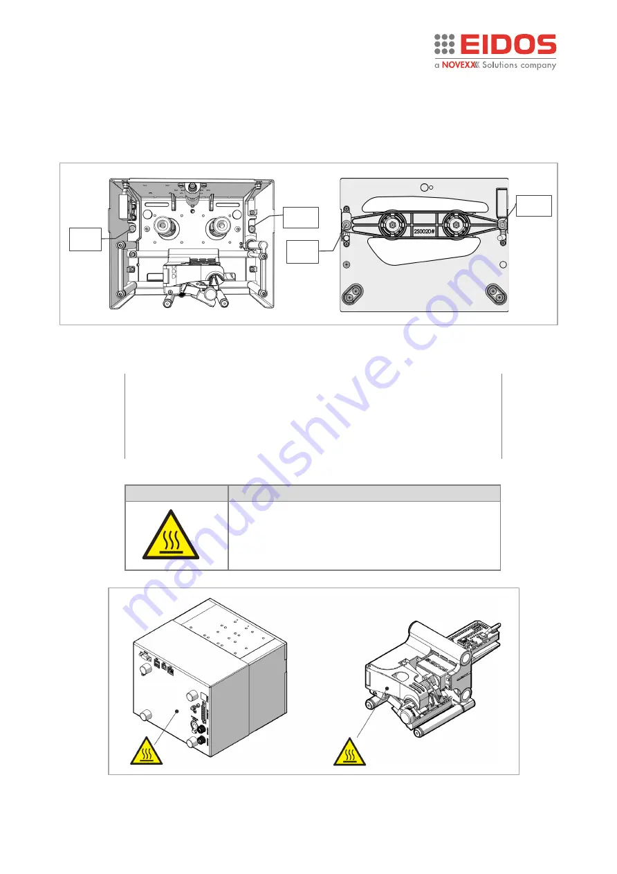
Magnets and magnets ring 

To ensure good fastening of the movable guard [RM1] to the XTO 2ie printing unit, magnets [mg1], 

[mg2] have been provided on the printer body and magnetic rings [am1], [am2] on the ribbon 

inserter. 


Warning symbols on the machine 

CAUTION! 

Warning symbols on the machine provide important information for the 

operating personnel. 

  Do not remove warning symbols. 

 Replace missing or illegible warning symbols. 

Meaning of the warning symbols: 

Warning symbol  Meaning 


The "Hot surface" symbol informs the operator and 

the staff assigned to the maintenance of the 

presence of potentially dangerous hot surfaces. 

Allow the device to cool off before touching it. 


Figure 15: warning symbols


mg2 

am2 

mg1 

am1 

Figure 14: magnets


Summary of Contents for EIDOS XTO 2.ie

Page 1: ...anual XTO 2 ie Edition A3 05 2021 Original Instructions keep for future reference RT800 USER MANUAL XTO 2 ie Intermittent Thermal Transfer Overprinter TTO This manual contains the EC Declaration of Conformity ...

Page 2: ......

Page 3: ...RMAL RIBBONS 24 PRINTING 25 CREATION AND SENDING OF THE LABEL WITH EASYCODE 26 HOW TO STORE LABEL FILES LM1 28 HOW TO BACK UP 28 SETTING AND MONITORING 29 STATUS MESSAGES 45 Preventive Maintenance 47 CLEANING INSTRUCTIONS 47 CLEANING THE PRINT HEAD 48 CLEANING THE PRINTING PLATE 48 CLEANING ROLLS AND RIBBON PASSAGES 49 CLEANING THE CARRIAGE SLIDING GUIDE 50 XTO 2 ie with XLS 20x labeller 51 SYSTEM...

Page 4: ...vice please use the return and collection systems available to you GENERAL NOTES Validity of this manual and required compliance This user manual refers exclusively to the electronic printer for thermal transfer to film named XTO 2 ie It is used for proper operation and adjustment of the printer The printer must be properly installed and configured to allow for operation and settings For informati...

Page 5: ...ode i e in safety conditions all possible movement prevented 3 The printer must not be used in an explosive environment or be used to treat explosive materials 4 The printer must not be used in irregular situations such as working without guards being correctly fitted to the machine working with products other than those prescribed 5 After 7 years of operation on an 8 hour daily shift a complete o...

Page 6: ... and bottom view Note During the installation it is necessary to fix the printing plate and the printing unit so that the plate prevents finger access to the areas A and B where the carriage with the print head moves Figure 1 dangerous areas on XTO2 ie front view s2 s1 S H T t X Y Figure 2 dangerous areas on XTO2 ie bottom view A B ...

Page 7: ...reas on XTO2 ie rear view Dangerous areas on XTO2 ie side views Dangerous areas on XTO2 ie carriage Figure 3 Dangerous areas on XTO2 ie rear view M2 M3 M1 Y U P X W P Figure 4 Dangerous areas on XTO2 ie side views Ct Sm t Figure 5 Dangerous areas on XTO2 ie carriage ...

Page 8: ...e when returning to Home after printing or during a return from Service Danger of crushing the fingers Y Movement of the carriage during printing or positioning in the Service area Danger of crushing the fingers P Rotation movement of the pulley and the belt for transmitting motion to the carriage W Rotation movement of the pulley and the belt for transmitting motion to the carriage Ct Print head ...

Page 9: ...ixed with screws WARNING Disconnect the 48Vdc power supply to the printer before removing the fixed guards RF1 RF2 RF3 The fixed guards must be removed only for extraordinary maintenance or repairs Movable interlocked guard RM1 Figure 7 fixed covers RF3 RF2 RF1 RM1 Figure 8 movable interlocked guard RM1 ...

Page 10: ... the areas A and B where the carriage with the print head moves On supports where there is an independent adjustment of the Printing Unit PU and the Printing Plate PP it is always necessary to maintain a relative position between the two parts that prevents access to dangerous areas Also to obtain a good print quality the print head must be positioned at a distance from the edge of the rubber laye...

Page 11: ...ts SAFETY_A and SAFETY_B SAF_EXT NOTE If not used they must be jumpered Not interlocked movable guard RM2 The guard is accessible only after removing the interlocked mobile guard RM1 SENS_C1 Figure 12 safety contacts SAF_EXT SAFETY_A SAFETY_B SAFETY_SAF Figure 13 guard RM2 Figure 11 monitoring sensors SENS4 Magnetic sensor ...

Page 12: ...the machine CAUTION Warning symbols on the machine provide important information for the operating personnel Do not remove warning symbols Replace missing or illegible warning symbols Meaning of the warning symbols Warning symbol Meaning The Hot surface symbol informs the operator and the staff assigned to the maintenance of the presence of potentially dangerous hot surfaces Allow the device to co...

Page 13: ...the USB memory stick PECULIARITY Print Unit very light and compact easy to be installed Easy to service and repair easy system of ribbon passage for changing operation Programmable printing steps and format printing parameters loadable by the touch screen display optional or the P C Improve unit uptime not necessary to uninstall the print unit from the line Modular assembly mechanic electronic Eas...

Page 14: ...lves to avoid noises and spikes Note The I O SIGNALS Junction Box 49KS0162 is not intended for Industrial use Figure 17 system models 45CV910 install on industrial power supply XTO2 ie 49KS0162 XTO2 ie 49KS0162 XTO2 ie 49KS0162 45CV897 1 L 7 m XTO2 ie 49KS0162 45CV897 1 L 7 m System Model 7XTO2I 2 System Model 7XTO2I 1 System Model 7XTO2I 3 System Model 7XTO2I 4 45CV910 1 capacitor kit to be conne...

Page 15: ...upply B RS232 connection it does not work on XTO printer C USB A USB B interface for label files exchange with USB memory stick disk A disk B D USB device for direct connection to the PC it does not work on XTO printer E LAN Network connection Ethernet 10 100 1000 F Ethernet POE port for EIDOS HMI connection XTO printer IP 10 0 0 1 not changeable G Digital 24V I O SIGNALS for print command anomaly...

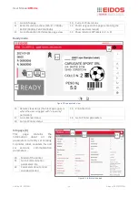
Page 16: ...owing browsers Chromium Raspberry Pi Chrome 18 and up Firefox 35 and up Safari 6 and up Edge 44 and up Main Functions Manual mode 1 Printer serial number 2 ESC button to select another printer or remote control panel 3 Printer data Current Date Current Time Progressive number Quantity number 4 Label view 5 Label Pan and zoom 6 Go to Parameters Setting menu 7 Load a new label this icon appears if t...

Page 17: ...mote view status the black eye appears when the user is logged with view only permission 16 Print direction 17 Go to Manual status 18 Go to Printer parameters 19 Current Printer status Info page 9 This page contains the information about all the parameters currently set relating to printer label counters fw and sw versions communication parameters 20 Model of the printer 21 Go to Communication par...

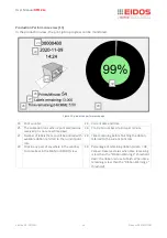
Page 18: ...bels that can still be printed with available ribbon referred to the current print rate 28 Time remaining before finishing the ribbon referred to the current print rate 29 Click in any part of anywhere in the window to come back in the MAN or READY view 30 Percentage of remaining ribbon Green OK Yellow Reserve status when time remaining is less than the Ribbon Warning 1 threshold Red the ribbon is...

Page 19: ...s operating features of the printer The password can be set for each user allowing access to the various levels Operator 1 and Expert Technician 2 The third level is for the Technical Assistance technician The User level 0 is not password protected and allows the operations necessary for the main printing operations At the first access to the menu all levels are freely accessible For greater secur...

Page 20: ... is also possible to rotate the label on the display attention just the image on the video not the direction of printing Note each time a different label is loaded it is advised to feed the ribbon to avoid printing over position Press the key reachable from the shortcuts page from Manual mode see point 12 of the figure in the chapter Control panel Main functions Manual mode of this manual Figure 2...

Page 21: ...viously saved packaging format parameters Every time you load a PAF file you update the printer parameters This function helps the operator to avoid incorrect printer settings By clicking on the button is it possible to view the current PAF parameter Note you can view the Paf without load it selecting the PAF file and clicking the icon By clicking on the button is it possible to set the current PA...

Page 22: ...h Variable From Printer the printing pitch for each track and the number of tracks N are set as printer parameters Track Number N this parameter defines the number of tracks N to be printed Tracks Pitch P Printing Pitches button between each track you can set different printing pitches P1 P2 P3 Repetition No this parameter can be set only when an LMT label file is loaded The LMT label file is a mu...

Page 23: ...eed must be done to avoid to avoid printing over position Press the key reachable from the shortcuts page from Manual mode see point 12 of the figure in the chapter Control panel Main functions Manual mode of this manual Printer Setup This menu allows adjustment of the basic parameters to make a fine adjustment without the risk of compromising the operation of the printer only 10 adjustment of the...

Page 24: ...ual XTO 2 ie Edition A3 05 2021 22 Operation Operation INSERTING CONSUMABLES How to load the thermal ribbon Figure 31 ribbon passage A2 A1 Biadhesive layer a b c 1 a b c 2 3 4 5 6 Figure 32 ribbon positioning d ...

Page 25: ...d immediately push the handle to position the ribbon on the shafts 5 Release the handle 6 Wait the ribbon feed operation Set the printer READY Restart the packaging line NOTE for 30 mm wide ribbon it is necessary to insert ring spacers 49KS0113 on the shafts XTO 2 ie requests to have ribbon centered to the print head The thermal ribbon reserve condition is reported on the basis of the diameter of ...

Page 26: ...ot enough 2 sufficient 3 discrete 4 good 5 excellent The rolls of thermal ribbon must be bought from the printer supplier in order to have the best possible guarantee of operating efficiency Using uncertified ribbons makes malfunctions highly likely and may greatly increase damage to the thermal head or cause dragging problems that are due to dirtying of the ribbon guide rolls Make sure you use th...

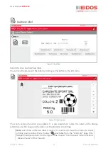
Page 27: ...Load the label to be printed Put the printer in MAN manual mode and click to the Load new label Operator data button Select the desired label choosing it from the disk flash CPU disk C or from disks A B USB memory stick Set any consecutive number and the variable data using the keyboard of the PC or HMI On the display check that the label and data entries are correct The zoom function is available...

Page 28: ...le data can be entered from keyboard recalled from a data base at the time of printing introduced by the operator on the printer and managed by the customer s program based on the E LIB Eidos tool for more information refer to the EASYCODE software manual Label copy from USB disk to XTO flash disk C With the EASYCODE software Liv 1 Demo version you can create modify save labels and copy them to EI...

Page 29: ...label with variable data from database With EASYCODE software DATABASE license version you can create modify save labels and send them to EIDOS and no EIDOS printers by means of their Windows driver via LAN network connection and manage variable data from database Microsoft Access mdb and accdb database files only How to operate Create the labels layout using Easycode Type the variable data from t...

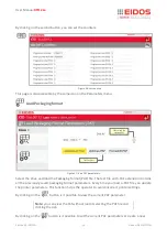
Page 30: ... menu levels have been assigned to different users HOW TO BACK UP Insert the memory key on which to store the data Put the printer in MANUAL mode and enter the Parameter Setting Click on File management button Click on Back up IMPORTANT Back up the data after printer installation is complete Repeat the backup procedure periodically in any case after making substantial changes to the parameters and...

Page 31: ...nter in the MAN position you access the parameter page where you can adjust the printer To access the desired level select the level from 0 to 3 on the left of the screen enter username and password and press Login The page for the selected level will appear on the display Figure 41 Login Figure 40 Pinter Parameter page Level 2 Lev 0 Lev 2 Lev 1 ...

Page 32: ...PORTANT The level 3 password is accessible only by specialized technicians and or by the technical assistance service For any information contact technical support Click on the button USER on the left menu the following page will appear on the display In this page the user data can be cancelled and a new user can be added by clicking on the button When adding a new user you must enter the username...

Page 33: ...e management Copy files or folders Delete files from disk Figure 44 copy files Figure 45 delete files Create directory the yellow background marks the folders Copy All menu Disk A and Disk B are the USB memory key inserted in the USB A and USB B connectors Disk C is the internal printer CPU disk ...

Page 34: ...utton Repeat the back up procedure periodically and in any case after making substantial changes to the parameters Note folders are highlighted in yellow New folder can be created by the button Restore Backup Insert the memory card in which the data was saved and click on Restore Back up button Figure 46 back up Figure 47 restore back up ...

Page 35: ...Edition A3 05 2021 33 Operation Set Printer Parameters This menu allows adjustment of the basic parameters after making the desired adjustments press the save button to make them effective Figure 48 Printer Parameter part A ...

Page 36: ...User Manual XTO 2 ie Edition A3 05 2021 34 Operation IMPORTANT by clicking on the button you can view the help of each parameter Figure 49 Printer parameter part B ...

Page 37: ...tomatically every minute or texts containing progressive numbering are updated without increasing the cycle time After Print the label is re processed at the end of print while the carriage is returning in home position Before Print this option will delay a little bit the print command execution recommended for labels with barcodes that contain date and time variables to be updated before every pr...

Page 38: ...e Printer diagnostic The buttons on the first grey strip allow you to view and adjust the diagnostic parameters Load new label a new label is loaded Label preview the label is displayed System diagnosis see following pages Figure 51 calendar Figure 52 diagnostic menu ...

Page 39: ...er Manual XTO 2 ie Edition A3 05 2021 37 Operation A D C B A Figure 54 diagnostic Yellow Input ON Grey Input OFF Figure 53 diagnostic Press to activate deactivate an OUTPUT Green Output ON Grey Output OFF ...

Page 40: ...s also accessible through the shortcuts on the Manual mode view if you have at least level 1 access See Product Description Operation Panel Figure 55 diagnostic Figure 56 diagnostic Yellow Input ON Grey Input OFF Press to make ON the internal led lamp Press to activate deactivate the Green lamp on front switch button Press to activate deactivate the Red lamp on front switch button ...

Page 41: ...status of the print head Print lines Print test of lines parallel to the print direction The lines are parallel to the print direction This test helps to verify the settling and the stability of the head on the media during print In case of bends it means that the print head support or the head alignment to the print roll or plate is not in the best condition or that the support is not stable Note...

Page 42: ... Print command check 0 disabled 1 enabled default End of Print FAP output type 0 pulse default It generates an impulse at the end of the cycle lasting 0 5 s 1 level At the start of the cycle arrival of the STA command it activates the FAP output and deactivates it at the end of the print when the TPH OFF time set in the parameters has elapsed Figure 58 I O management 0 1 2 3 PULSE LEVEL ...

Page 43: ...enerated Enable Page I O 0 disabled 1 from disk C A B 2 from disk K To enable this flag means that the labels 0 LM1 15 LM1 previously stored in the printer memory can be selected via 4 digital inputs these 4 opto isolated inputs are available on the ENCODER port of the printer Set IP parameters If the Wait Ready function is enabled W character is emitted when the print cycle starts and R character...

Page 44: ...RTANT it is advised to make the TPH calibration with the packaging film overposed on the printing plate to take in account the thickness of the film Figure 60 ETH LAN Figure 61 TPH calibration Shows the value during the calibration Shows the current value during the calibration ...

Page 45: ...e between 74 77 If the detected value is higher than 80 the W562 warning will appear because the print head is too far from the printing plate If the detected value is less than 69 the W567 warning will appear because the print head is too close to the printing plate The higher the detected value the higher the angle of the print head is during printing During calibration the print head moves to t...

Page 46: ...e ZPL file to get in print the correct image size Custom CSE command enable this flag if you need a custom EIDOS printer management You can manage a EIDOS printer as ZEBRA for the data to be printed and as EIDOS printer for the status request and wait ready protocol With this flag enabled some EIDOS CSE commands will be also managed when the Zebra Emulation is enabled Ignore ZPLII Label dimensions...

Page 47: ...f the message appears in MANUAL mode it must be unlocked to go to READY mode and allow printing The status report shown on the display is structured as follows A Alarm icon Press the key below the symbol to unblock the status message B Warning number C Warning message D Background colour Yellow E Help icon After pressing the icon a quick troubleshooting guide appear F Pause It unlocks the message ...

Page 48: ...icon a quick troubleshooting guide appear F Pause It unlocks the error message not the error to allow access to the diagnostic pages The error will appear again when the operator comes back to the main pages G Error text Each error number has a status text in the language of the control panel I Diagnosis icon Pressing the button you are sent to the appropriate diagnostic page G I Figure 67 trouble...

Page 49: ...nnecting line Never allow liquid to get into the machine Repairs to the machine must only be made by trained service technicians Cleaning agents CAUTION Sharp cleaning materials may damage the printer Do not use any cleaning agents or materials that could damage or destroy the paint finish labelling display type plates electrical component etc Do not use abrasive cleaners or cleaners which could d...

Page 50: ...ver 2 Move the carriage manually to have easy access to the head area from the top 3 Clean the printing line L with a clean tissue or with a paper cleaning tissue soaked in isopropylic alcohol On no account use metal objects or any hard material CLEANING THE PRINTING PLATE Clean with a cleaning tissue or with a paper tissue soaked in isopropyl alcohol Advisable when the printer is in fixed positio...

Page 51: ...d is not crooked How to operate 1 Use a jet of low pressure air to clean the dust off the printing unit 2 Use a tissue or a paper tissue soaked in isopropylic alcohol to clean all the rolls and ribbon passages 3 If necessary lubricate the bushes with Ballistol oil Pay attention do not dirty with oil the surface of rolls On no account use jets of water or steam to clean the printer Figure 69 cleani...

Page 52: ...for its entire path forwards backwards three or four times and re clean guides with clean cloth to dry any excess oil WARNING DO NOT use other lubricants or grease as they clog the bushes with the guides and compromise carriage movement Any maintenance or repair tasks that are not prescribed in this manual must be performed only by EIDOS or by an Authorized Service Centre Figure 71 cleaning the sl...

Page 53: ...r any technical questions you may have that are not described in this manual see The technical manual of the XTO 2 ie Printer The user manual and the service manual of the labeller XLS 20x or Request a technical service SYSTEM CONFIGURATION The system is available as right hand RH or left hand LH version A Left LH version B Right RH version C Product on the conveyor belt D Labelled product E XTO t...

Page 54: ...y voltage of the labeller and XTO 2 ie refer to the relative instruction manual XLS 20x switching on and off Set the main switch A to I XTO 2 ie switching on and off Click the ON OFF button B Figure 74 labeller main switch LH version RH version Print start Print start the green arrows indicate the printing direction Figure 73 printing direction B Figure 75 printer switching ...

Page 55: ...TO 2 ie print time When XTO 2 ie goes in error eg foil end it activates the ANM output that is connected to XLS ERROR input So in case of XTO 2 ie error XLS immediately stops and shows the error S124 PLC error input When XTO 2 ie has a warning eg foil close to end it activates the RIS output that is connected to XLS warning input So the PLC warning message appears on the XLS 20x display If the pri...

Page 56: ... label dispenser is designed to be maintenance free However you should service the unit reg ularly in order to ensure reliable long term operating results Cleaning interval Clean machine regularly The frequency depends on the following factors Operating conditions Daily operating duration Removing paper debris Depending on operating conditions you should perform the following at least once a week ...

Page 57: ...Applied standards UNI EN ISO 13857 2020 safety distances CEI EN 60204 1 2006 on the safety of electrical equipment Electromagnetic compatibility standard EMC 2014 30 EC Applied standards EN 55032 2015 Electromagnetic compatibility of multimedia equipment Emission Requirement EN IEC 61000 6 2 2019 Electromagnetic compatibility EMC Part 6 2 Generic standards Immunity for industrial environments EN 6...

Page 58: ...ual XTO 2 ie Edition A3 05 2021 56 Appendix 2 Appendix 2 CE LABEL 1 System model 2 Mechanical unit 3 Electronic unit 4 Serial number 5 Production date CE Label position on Mechanical Unit Attach the label here ...

Page 59: ...Thank you for taking the time to read this manual we recommend you keep it for future reference ...

Page 60: ...Via dell Industria 11 Z I Fontaneto 10023 Chieri TO ITALY e mail eidos eidos eu web www eidos eu ...

Reviews: