background image


8

/

30


N-LINE OWNERS MANUAL 

9


Installation 

The N-Line consists of 3 models: Panel mount, Vesa Mount and Rear Mount. The first part of this chapter describes the universal 
installation of all models.  Please refer to the corresponding paragraphs below for more detailed mounting description per 
model. 
 
Before installation check the power source to be compatible with the power input of your monitor. 
 

9.1


Mounting the monitor 

When installing the monitor first make sure to determine the right place. There should be sufficient airflow at the back of the 
monitor when using the panel mount version. For any model always make sure that there is no direct sunlight on the monitor. 
This might heat-up the unit too much. 


Determine location in compliance with the minimum radar distance mentioned on the back side of the monitor 


9.1.1


Panel mount 

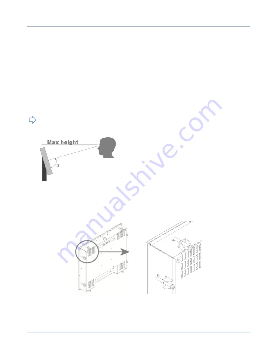
The monitor is supplied with mounting brackets for all mounting positions. All brackets need to be installed as shown in figure 
below to ensure safe and rigid mounting. 


Please follow these steps for successful installation of the panel mount monitor 


Locate the right position for the monitor and take following in account: 

o


Leave space around the monitor to ensure sufficient airflow for cooling to meet the temperature specifications 
mentioned in this manual 

o


Mount the monitor in an angled position (≥ 35° from horizontal) to ensure airflow through the monitor  

o


Make sure that there is enough airflow (cooling) in the desk. Install a cooling fan if necessary. 

 IEC 

Viewing angle is an theretical value measured 
with standard colors and contrast. In real life 
the monitor should be installed with angle: 120 
< α < 90. This means that viewing from bottom 
side should be avoided. For viewing 
convenience install the monitor below eye-
level (max height). 
 

Summary of Contents for N-LINE

Page 1: ...OWNERS MANUAL NOTTROT BV Raamsdonksveer Nederland For more information please visit www nottrot nl or call 31 162 515458 Ref 1013M01V1 4 N LINE PANEL MOUNT DESKTOP REARMOUNT ...

Page 2: ...OSD 14 9 7 Projected capacitive touch screen 15 10 Maintenance 15 11 Trouble shooting 16 11 1 Power 16 11 2 Image 16 11 3 Touch screen 16 12 Specifications 17 12 1 Video 17 12 1 1 Compatibility and video standards 17 12 1 2 Applicable Graphic Mode 17 12 2 Dimensions K KE KG and KGE models 18 12 3 Dimensions D and DE models 19 12 4 Dimensions R models 19 12 5 Electrical and environmental 20 12 6 Mo...

Page 3: ...P 3 30 N LINE OWNERS MANUAL 16 2 Warranty Exclusions and Disclaimer 29 16 3 Obtaining Warranty Service 30 ...

Page 4: ... are using the latest version of this manual when installing a new product Although we strive to be as complete as possible there will always be additions made All updates of this document are subject to change without notice The revision history is shown in chapter 1 3 Disclaimer Nottrot BV makes no representations or warranties either expressed or implied with respect to the contents hereof and ...

Page 5: ...30VAC 12VDC N a with 9 36VDC input option Mains cord Euro style Only with external power adapter VGA cable 15p HD Sub M M DVI Cable Optional RS 232 cable Optional touch M F USB cable Optional touch A B Touch driver software Optional touch Mounting brackets with M5x50 screws and M5 nuts Panel mount model only Mounting brackets with M4 screw Rear mount model only na Optional cables External central ...

Page 6: ...full glass front NxxxKGE 1 Panel mount full glass front extended bezel at bottom side for controls or dim knob NxxxD VESA mount metal bezel NxxxDE VESA mount metal bezel extended bezel at bottom side for controls or dim knob NxxxDG VESA mount full glass front NxxxDGE VESA mount full glass front extended bezel at bottom side for controls or dim knob NxxxR Rear mount no front optional touch or glass...

Page 7: ...void short circuit Make sure no fluids can enter the units through the ventilation gaps Wait for at least 6 seconds after switching power off before removing the cables Make sure the temperatures do not exceed max values when storing or using the display When an image is displayed over a long period this can be from 1 week up to 1 month the image can stick to the surface of the TFT front This can ...

Page 8: ...n the back side of the monitor 9 1 1 Panel mount The monitor is supplied with mounting brackets for all mounting positions All brackets need to be installed as shown in figure below to ensure safe and rigid mounting Please follow these steps for successful installation of the panel mount monitor Locate the right position for the monitor and take following in account o Leave space around the monito...

Page 9: ...ew to the bracket The VESA mount option is not part of certification 9 1 2 VESA mount The desktop models can be mounted on any mounting bracket or pedestal corresponding with the right VESA mounting interface standard Please refer to the dimensional drawings in this manual Use M4 screws max insert in the monitor is 8mm 9 1 3 Rearmount The rearmount monitor is supplied with sufficient brackets incl...

Page 10: ...iption Dim knob Dimming knob 1 Potentiometer for backlight brightness rotate CW to increase and CCW to decrease 2 Multifunction knob o rotate CW to increase and CCW to decrease o Push for standby modus power ON OFF Capacitive switch for Source select Touching the glass at the symbol will select the next video input In the OSD menu you can switch unused sources to OFF to avoid scrolling through unu...

Page 11: ...djust the vertical position of the screen s image Clock Adjust the horizontal size of the screen s image Phase Adjust the focus of the screen s image Auto Automatically adjust the Horizontal position Vertical position Window s background or characters should be displayed on your full screen prior to precede this function 3D NR Select NR mode Standard Strong Auto Off Weak Menu Language Select the O...

Page 12: ...O Signal source RGB DVI Picture Mode Standard Dynamic Soft Personal Contrast 0 100 Brightness 0 100 Backlight 0 100 Sharpness 0 100 Color Mode Normal Warm Cool User R G B Auto Color Advanced H Pos V Pos Clock Phase Auto Signal source CVBS HDMI Picture Mode Standard Dynamic Soft Personal Contrast 0 100 Brightness 0 100 Backlight 0 100 Sharpness 0 100 Tint 50 50 Color 0 100 Color Mode Normal Warm Co...

Page 13: ...ain menu Sub Menu Sleep Timer OFF 240 MIN Zoom Mode Normal Wide Zoom for CVBS HDMI Normal Wide or RGB DVI Image Flip ON OFF Image Mirror ON OFF Auto Source ON OFF XGA Mode 1024x768 1280x768 1360x768 1366x768 HDMI Mode PC Video No Overscan ...

Page 14: ...ion it could be that the knob is still in the OSD modus In that case wait for 10 seconds before using the knop again Symbol Encoder External Buttons Switch function of encoder press knob to activate Middle button Increase rotate CW Right button Decrease rotate CCW Left button Press for 10 sec to enter OSD Press or to scroll through the menu items Press or to adjust parameter Desired item No Press ...

Page 15: ...arts inside the monitor When the monitor is used in its intended environment there is not much maintenance needed Please follow these directions Turn off the product and disconnect from the power source before cleaning or maintenance To reduce the risk of electric shock follow all safety notices and never open the touch monitor case Avoid dust and water to enter the monitor and never open the moni...

Page 16: ...e on the screen Video source cable not connected securely Wrong source mode Check proper fitting of the video cables Check the video source PC monitor etc to be powered and connected correctly Is the Video source set to ON in the Source Setting OSD menu Image colors are not shown right Missing color in the video source Check proper fitting of the VGA connector Image is not positioned correctly not...

Page 17: ... board Serial Control RS232C ready Customized protocol setting optional contract basis 12 1 2 Applicable Graphic Mode The microprocessor measures the H sync V sync and V sync H sync polarity for RGB inputs and uses this timing information to control all of the display operation to get the proper image on a screen The monitor can detect all VESA standard and MAC Graphic modes shown on the table bel...

Page 18: ...60X768 60Hz 85 00 VESA P 47 712 1792 1360 P 60 015 795 768 1600x1200 60Hz 160 875 VESA N 74 479 2160 1600 P 59 967 1242 1200 1680x1050 60Hz 147 000 VESA N 65 160 2256 1680 P 59 944 1087 1050 1920x1080 60Hz 172 750 VESA N 67 061 2576 1920 P 59 983 1118 1080 1920X1200 60Hz 193 125 VESA N 74 508 1292 1920 P 59 990 1242 1200 12 2 Dimensions K KE KG and KGE models Model A K KG A KE KGE B C K KE C KG KG...

Page 19: ...100 MIS E N240 X 384 2 567 0 32 X 34 173 3 100 MIS E N420 569 9 X 977 2 5 X 61 207 5 600x200 M6 X Not available yet 12 4 Dimensions R models Model A B C D N104 188 8 239 8 59 0 292 8 N106 173 265 6 59 0 318 6 N150 266 5 340 5 59 0 393 5 N154 243 0 366 0 59 0 419 0 N170 302 9 374 3 59 0 427 3 N190 336 6 410 0 59 0 463 0 N230 324 6 547 2 59 0 600 2 N240 362 6 564 4 59 0 617 4 N420 567 1 974 2 86 5 1...

Page 20: ...se contact us Item Item Min Max Unit Power DC Input 12VDC plug 11 0 13 0 VDC Ext DC Power 9 0 35 0 VDC Desktop PSU Input voltage 100 240 VAC Input Current 1 8A 230VAC A Frequency 50 Hz Output voltage 12 VDC Output current 5 A IP rating NxxxK NxxxKE Front only IP55 NxxxKG NxxxKGE Front only IP65 NxxxD NxxxDE NxxxDG NxxxDGE Na Storage tempereature 20 60 C ...

Page 21: ...00 1000 1500 700 760 1500 1500 1000 1000 4000 Native Brightness Cd 450 1000 500 400 400 280 330 300 300 500 Max power W 3 tbd 25 tbd tbd tbd tbd tbd tbd tbd tbd Enhanced Brightness Cd 1000 na 800 800 800 800 800 800 1000 Max power W 3 tbd na tbd 30 tbd tbd tbd tbd tbd tbd Ultra high brightness 1500 Max power W Storage temperature 20 65 20 65 20 65 20 65 20 65 20 65 20 65 20 65 20 65 20 65 Operatin...

Page 22: ...d 15 DDC SCL 19 HP Detect 4 Data1 8 Data0 Shield 12 CLK 16 DDC SDA VGA Input D SUB 15Pin R L row wise Pin Function Pin Function Pin Function Pin Function Pin Function 1 Red 4 NC 7 GND 10 GND 13 HSYNC 2 Green 5 Check Signal 8 GND 11 NC 14 VSYNC 3 Blue 6 GND 9 NC 12 DDC_SDA 15 DDC_SCL 12 VDC input plug Pin Function Pin Function Pin Function Pin Function Pin Function 1 12VDC 2 Detect 3 GND This optio...

Page 23: ...r S 18 OSD Power 24 GND This option is not part of certification Light sensor LDR HRS xxxx series L R Pin Function Pin Function Pin Function Pin Function Pin Function 1 Wire 1 2 Wire 2 This option is not part of certification Potentiometer external dimming HRS XXXXX CCW Pin Function Pin Function Pin Function Pin Function Pin Function 1 V 2 Vbr 3 V This option is not part of certification Increment...

Page 24: ...of pixels or sub pixels which are either a Permanently dark or light which is not always evident OR b A constant flash which is more noticeable Fortunately there is an ISO 13406 2 Class II standard which covers the maximum number pixels on any given panel There are 4 classes Class I monitors are guaranteed products which do not have any defects at all Class II specification consists of the followi...

Page 25: ...his is caused by ions polluting the material Liquid Crystal Displays are made of and thus will occur on all LCD s TFT is the name for the most common used technology in LCD s Image Sticking is a slow build up of energy ions in pixels that are statically turned on in a LCD This energy will eventually keep the pixel slightly on and so cause Image Sticking on the display Image Sticking and the specia...

Page 26: ...em is not active 2 Run LCD s at maximum 80 brightness and contrast the reduction will only be seen as an 8 reduction in light level to the human eye 3 Create panning images to prevent static lines and text building up Boundary Image Retention 4 Use soft colors light grey dark grey light yellow a s o 5 Check displays for Boundary Image Retention using a 50 grey and imply on of guidelines 1 to 4 whe...

Page 27: ...007 Information technology equipment Radio disturbance characteristics Limits and methods of measurement EN 55024 1998 Amd A1 2001 Amd A2 2003 Information Technology Equipment Immunity Characteristics Limits and methods of measurements EN 61000 3 2 2006 Electromagnetic compatibility EMC Part 3 2 Limits Limits for harmonic current emissions equipment input current 16 A per phase EN 61000 3 3 1995 A...

Page 28: ...P 28 30 N LINE OWNERS MANUAL 15 2 IEC 60945 ...

Page 29: ...onitor or other misuse abuse or negligence to the monitor b by the use of parts not manufactured or sold by Nottrot c by modification of the monitor d as a result of service by anyone other than Nottrot e by improper transportation or packing when returning the monitor to the Point of Sales POS reseller or f by improper installation of third party products e g objectives 3 any monitor or parts the...

Page 30: ...rot its supplier an authorised Nottrot representative service provider or dealer have been advised of the possibility of such damages or of any claim by any third party Any liability of Nottrot or its supplier which is not excluded shall be limited to the purchase price of the monitor 16 3 Obtaining Warranty Service Your Nottrot Warranty includes a Carry In warranty service The warranty service wi...

Reviews: