SFP-400B 15124:G1 06/24/97
7
1.3
Optional Boards
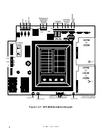
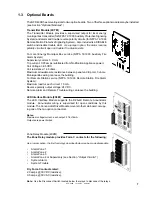
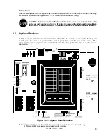
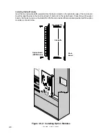
The SFP-400B has mounting slots for two option boards. Two of the three option modules may be installed.
(see Section
"Optional Modules" )
Transmitter Module (4XTM)
The Transmitter Module provides a supervised output for local energy
municipal box transmitter (for NFPA 72-1993 Auxiliary Protective Signaling
System) and alarm and trouble reverse polarity circuits (for NFPA 72-1993
Remote Station Protective Signaling System). Also included is a DISABLE
switch and disable trouble LED.
As a jumper option, the alarm reverse
polarity circuit will open on trouble if no alarm exists.
For Local Energy Municipal Box service (NFPA 72-1993 Auxiliary Fire
Alarm System)
Supervisory current: 5.0 mA.
Trip current: 0.35 amps (subtracted from Notification Appliance power).
Coil Voltage: 3.65 VDC.
Coil resistance: 14.6 ohms.
Maximum allowable wire resistance between panel and trip coil: 3 ohms.
Municipal Box wiring can leave the building.
For Remote Station service (NFPA 72-1993 Remote Station Fire Alarm
System):
Maximum load for each circuit: 10 mA.
Reverse polarity output voltage: 24 VDC.
Remote Alarm and Remote Trouble wiring can leave the building.
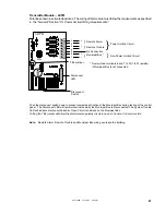
LED Interface Module (4XLM)
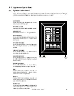
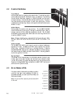
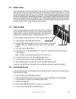
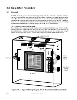
The LED Interface Module supports the RZA-4X Remote Annunciator
module. Annunciator wiring is supervised for open conditions by this
module. The Annunciator Driver Module mounts to the main board, occupy-
ing one of the two option connectors.
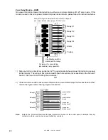
Zone Relay Module (4XZM)
The Zone Relay module provides Form-C contacts for the following:
As a jumper option, the first four relays described below can be made silenceable.
•
Alarm Zone 1
•
Alarm Zone 2
•
Alarm Zone 3
•
Alarm Zone 4 or Supervisory (see Section
"Output Circuits" )
•
System Alarm
•
System Trouble
Dry Form-C contacts rated:
2.0 amps @ 30 VDC (resistive),
0.5 amps @ 30 VAC (resistive).
Note: Use the Disconnect Switch located below the relays to disconnect the relays.
Notes:
Maximum voltage/current, each output: 27.6V/8mA.
Outputs are power limited.


