


SFP-400B 15124:G1 06/24/97
14
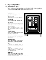
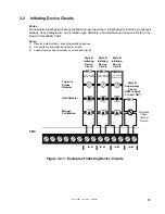
3.1
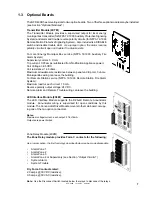
General
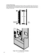
Carefully unpack the system and check for shipping damage. Mount the cabinet in a clean, dry, vibration-
free area in which extreme temperatures are not encountered. The location should be readily accessible
with sufficient room for easy installation and maintenance. Locate the top of the cabinet approximately five
feet above the floor with the hinge mounting on the left. Determine the number of conductors required for
the devices to be employed. Pull required conductors into the box through the knockout provided. All wiring
should be in accordance with the National and/or Local codes for fire alarm systems.
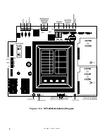
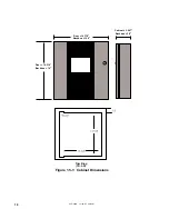
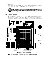
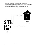
UL Power Limited Wiring Requirements
Power limited and non-power limited circuit wiring must remain separated in the cabinet. All power limited
circuit wiring must remain at least 0.25" away from any non-power limited circuit wiring. Furthermore, all
power limited circuit wiring and non-power limited circuit wiring must enter and exit the cabinet through
different knockouts and/or conduits. A typical wiring diagram for the SFP-400B is shown below.
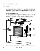
3.0 Installation Procedure
PC Board
AC Power
Figure 3.1-1: Typical Wiring Diagram for UL Power Limited Requirements
Initiating Circuits
Bell Circuits
Power Limited Circuits
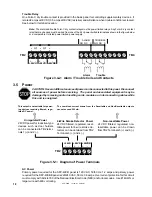
Power
Limited
Circuit
Non-Power
Limited
Circuit


