background image

38

NFS2-640/E Operations Manual —

 P/N 52743:F1  06/16/2011

Read Status Operation

Viewing and Printing a Read Status

Device Status

 The status of the module: control/relay module [On (device active) OFF (device 

not active] or monitor module (Normal, Alarm, or Test).

Type Code

 The software Type Code that identifies the type of module. (Refer to “Point 

Programming” in the 

NFS2-640 Programming Manual

.)

CBE list

 Only the first zone in the device’s CBE list will be displayed.

Device SLC Address

 The SLC address of the module.

Switch Inhibit (control/relay module only)

 Displays whether the remote ON/OFF capability 

of the device is inhibited. (I=on; *=off).

Silenceable (control/relay module only)

 A selection that specifies if the device can be 

silenced during an alarm by pressing the signal silence key. Possible values are: 

*

 = output nonsilenceable

F

 = silenceable, resound by fire alarm

U

 = silenceable, resound by supervisory alarm

B

 = silenceable, resound by security alarm

T

 = silenceable, resound by trouble

O

 = silenceable, does not resound

Walk Test (control/relay module only)

 A selection that specifies if the device will activate 

during a Walk Test.

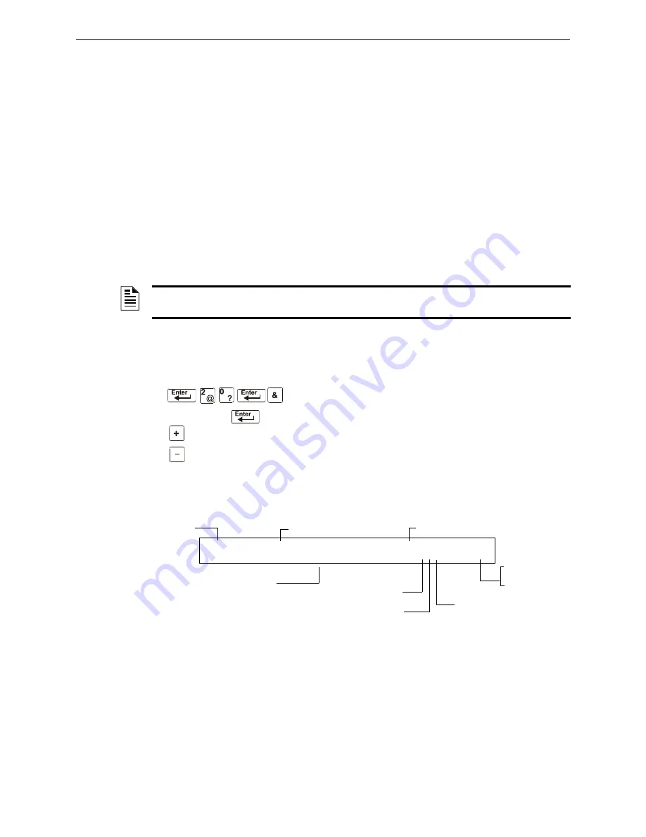
How to View Read Status for a NAC

From the “Read Status” screen, press 

0

, then press the 

ENTER


key. You can now view Read Status for a NAC as follows: 
press 

OUTPUT

, enter the device address, then press the 

ENTER


key. For example, to read the status of NAC 0-2: press 

OUTPUT

, enter 02, then press the 

ENTER

 key. The control 

panel now displays information for a NAC as shown in 
Figure 4.3.

The display and descriptions of the fields are shown below: 

Figure 4.3  Sample NAC Read Status Display

Device Status

 The status of the device: ON (device active) OFF (device not active).

Type Code

 The software Type Code that identifies the type of NAC. Refer to “Appendix F - 

Type Codes” in 

NFS2-640 Programming Manual

.

CBE List

 Only the first zone in the NAC’s CBE list will be displayed here.

Device Address

 The address of the NAC (01-04)

Switch Inhibit

 A selection for disabling the switch function for the control/relay or 

transponder output circuit. (

I

=on; 

*

=off).

NOTE:

If the “Strobe” Type ID is used with System Sensor Strobe synchronization, F, U, B, T, or 

O will silence the entire circuit, “*” will silence the horn portion only.

Device address

           next device

           previous device

Type Code (CONTROL)

Walk Test selection:

selected for Walk Test

 * 

not selected

Label for the NAC

Default zone selection

Address (01-04)

B

 = NAC

Switch Inhibit:

 I

 selected,

 *

 not selected

Device status

Silenceable:

 O =

 selected, 

* = 

not selected (default)

O F F           C O N T R O L             F R O N T   H A L L W A Y   N O .   2

                              Z 0 0 0                       * O W         B 0 2

Summary of Contents for NFS2-640

Page 1: ...F1 P N 52743 F1 ECN 11 336 Document 52743 06 16 2011 Rev Fire Alarm Control Panel NFS2 640 E Operations Manual...

Page 2: ...fire Smoke detectors cannot be expected to provide adequate warning of fires caused by arson children playing with matches especially in bedrooms smoking in bed and violent explosions caused by escapi...

Page 3: ...iling reaming or punching of the enclosure When possible make all cable entries from the sides or rear Before making modifi cations verify that they will not interfere with battery trans former or pri...

Page 4: ...priate version for a specific application Documentation Feedback Your feedback helps us keep our documentation up to date and accurate If you have any comments or suggestions about our online Help or...

Page 5: ...5 Security Alarm Mode of Operation 21 3 5 1 How the Control Panel Indicates a Security Alarm 21 3 5 2 How to Respond to a Security Alarm 22 3 5 3 Interpreting Security Type Codes 22 3 6 Active Superv...

Page 6: ...Releasing Zones 49 A 2 2 How to View Releasing Zone Selections 50 A 2 3 How Releasing Zones Operate 50 A 3 Time Date and Holiday Functions 52 A 3 1 Overview 52 A 3 2 How to View Time Control Selection...

Page 7: ...Status 65 C 4 1 Overview 65 C 4 2 Accessing Alter Status Options 65 C 4 3 Enable or Disable Detectors Modules or Zones 66 C 4 4 Change Alarm and Pre Alarm Levels 66 C 4 5 Clear Verification Counter 6...

Page 8: ...use irreversible damage to the control panel irreversible loss of programming data or personal injury When you see Specifies Example text in small caps the text as it appears in the LCD display or on...

Page 9: ...ry Peripherals Enclosure Installation Document 50295 Power Supplies Auxiliary Power Supplies Battery Chargers Document Number ACPS 610 E Instruction Manual 53018 ACPS 2406 Installation Manual 51304 AP...

Page 10: ...arm Activate functions through monitor modules Automatic time of day and day of week control functions with holiday option Intelligent Sensing with nine field adjustable Pre Alarm levels with programm...

Page 11: ...on page 14 Control Keys Refer to page 12 Status Indicator LEDs Refer to Section 2 2 below Programming Keypad Refer to page 14 Function keys Refer to page 14 Cursor movement arrow keys ESC key and ENT...

Page 12: ...Clear the alarm condition and reset the system PRE ALARM Red Flashes when a non acknowledged fire Pre Alarm exists Lights steadily after you acknowledge the Pre Alarm Clear the pre alarm condition An...

Page 13: ...ESET key to reset the control panel When pressed the control panel does the following Clears ALL active inputs Interrupts resettable power Sends a System Reset message to the History buffer and instal...

Page 14: ...l control panel LEDs Turns on the panel sounder Lights all segments of the LCD display When the LAMP TEST key is held for longer than five seconds the LCD will display the Software Revisions 2 4 Progr...

Page 15: ...em in a list or display the device at the next highest address PREVIOUS SELECTION key press to display the previous item in a list or display the device at the next lowest address Arrow keys press to...

Page 16: ...Mode of Operation page 16 3 3 Fire Alarm Mode of Operation page 17 3 4 System Trouble Mode of Operation page 19 3 5 Security Alarm Mode of Operation page 21 3 6 Active Supervisory Signal Mode of Oper...

Page 17: ...hat activated the fire alarm Displays ALARM in the status banner on the LCD display along with information specific to the device as shown below Figure 3 2 Sample Fire Alarm Display Sends an Alarm mes...

Page 18: ...ion Lights FIRE ALARM LED and activates CBE HEAT DETECT Y Indicates activation of a conventional heat detector Lights FIRE ALARM LED and activates CBE MONITOR Y Indicates activation of an alarm monito...

Page 19: ...of a 190o F intelligent thermal detector Lights FIRE ALARM LED and activates CBE HEAT Y Indicates activation of a 190oF adjustable threshold intelligent thermal detector Lights FIRE ALARM LED and acti...

Page 20: ...nowledge Message 3 Check the trouble message for the location and type of trouble Figure 3 6 Sample Trouble Messages on CRT 2 or Printer 4 Correct the condition causing the trouble If the trouble clea...

Page 21: ...display 3 5 Security Alarm Mode of Operation 3 5 1 How the Control Panel Indicates a Security Alarm The system goes into Security mode when a monitor module point programmed with a Security Type Code...

Page 22: ...ity alarm message indicates the type of security alarm being generated by the monitor module that initiates the alarm For example a monitor module with a Type Code of AREA MONITOR indicates an intrude...

Page 23: ...Normal message to the LCD display remote annunciators history buffer installed printers and CRT 2s If Non latching Type Code Displays Some Supervisory Type Codes do not latch the control panel Refer...

Page 24: ...ates supervisory non alarm condition Lights SUPERVISORY LED and activates CBE SUP L DUCTI Y Ion detector that indicates supervisory non alarm condition Lights SUPERVISORY LED and activates CBE SUPT DU...

Page 25: ...ample of an Alert Pre Alarm Message An Alert Pre Alarm automatically restores to normal when the detector sensitivity programmable to one of nine settings drops below the programmed Alert level Zone F...

Page 26: ...devices associated with the zone Disable message Type Code of the disabled device Address of the disabled device DISABL TAMPER INTENSIVE CARE UNIT EASTERN WING 03 20P 041508 1M159 Custom descriptor fo...

Page 27: ...he lights down without any audio or visual indication on the control panel 3 10 CO Alarm Mode of Operation 3 10 1 How the Control Panel Indicates a CO Alarm When an initiating device detector or monit...

Page 28: ...ry buffer and installed printers FDU 80 annunciators and CRT 2s 3 10 3 Interpreting CO Alarm Supervisory Type Codes The Type Code that displays in the CO Alarm message indicates the function of the po...

Page 29: ...l sends an Acknowledge message to the History buffer and installed printers FDU 80 annunciators and CRT 2s Check the trouble message for the location and type of trouble 3 Correct the condition causin...

Page 30: ...puts to perform a releasing function REL CKT ULC N NAC Directs outputs to perform a release function as required by ULC REL AUDIBLE N NAC NAC activated upon release NONRESET CTL N NAC Relay output una...

Page 31: ...ific to the device Figure 3 2 Sample of a Control Relay Module in Trouble Message 3 12 4 How to Respond to a NAC or Control Relay Trouble If the control panel indicates an active NAC or Control Relay...

Page 32: ...ence Timer reaches its programmed value 600 900 seconds the control panel automatically shuts off all active outputs programmed as silenceable Alarm Verification Timer A timer that directs the control...

Page 33: ...to the NFS2 640 Installation Manual for information on Waterflow circuits 3 15 Style 6 and Style 7 Operation Style 6 and Style 7 are supervised methods of communicating with addressable devices If the...

Page 34: ...while a fire alarm or trouble condition exists 4 2 1 Quick Reference Key Sequences For quick reference in the left margin next to each Read Status option is a block that shows the key sequence needed...

Page 35: ...e Print Points 1 key ENTER key Print information for all installed points in the system Read History 2 key ENTER key Display the total number of events in the History buffer and step through each even...

Page 36: ...r a Detector From the Read Status screen press 0 then press the ENTER key You can now view Read Status for a detector as follows press DETECTOR enter the SLC number followed by the three digit address...

Page 37: ...combines the detector s alarm decision with the next SLC address above and the next SLC address below Alarm Verification or V Alarm Verification not programmed for this detector V Alarm Verification...

Page 38: ...ad Status screen press 0 then press the ENTER key You can now view Read Status for a NAC as follows press OUTPUT enter the device address then press the ENTER key For example to read the status of NAC...

Page 39: ...View Read Status for a Special Zone F0 F9 FA FC From the Read Status screen press 0 then press the ENTER key You can now view Read Status for a Special Zone as follows press Z enter the zone number F...

Page 40: ...ess Z enter S0 press the ENTER key Shown below is a sample display and description of items for the Read Status of System Functions Releasing Zone Number next device previous device Zone label for Rel...

Page 41: ...r Selections 3 and 4 Screens LocT One of three operating modes of a PC or terminal connected to the control panel through TB12 PC Terminal LocT terminal connected to control panel and located in the s...

Page 42: ...y Security 2 turn on by Supervisory BAT_SIZE 1 battery size is greater than 26 Ahr 0 less than 26 Ahr C_DRILL custom drill N No custom drill Y Yes TERM_DATA 0 LCD80 Terminal using 7 bit data 1 LCD80 T...

Page 43: ...points Zones 1 56 B Zones 57 99 9 F zones 8 R zones 4NAC C Loop 1 Modules 1 64 D Loop 2 Modules 1 64 E Loop 1 Modules 65 128 F Loop 2 Modules 65 128 G Loop 1 Modules 129 159 Loop 2 Modules 129 159 H L...

Page 44: ...and Printing a Read Status How to Read Status for Battery Levels Pressing the BATTERY LEVEL key on the NFS2 640 keyboard displays information concerning the state of the battery A sample LCD display i...

Page 45: ...sequence From the Read Status screen press 2 then press the ENTER key to display the Event History screen A sample of the Event History screen is shown below Figure 4 16 Sample Event History Display T...

Page 46: ...play 4 4 3 How to Print Points Event and Alarm History Overview Read Point options 1 3 and 5 in the Read Status screen let you print points event history and alarm history This section contains instru...

Page 47: ...ory Print option How to Print Alarm History Option 5 ALARM HIST 5 lets you print a list of alarm events in the History buffer up to 200 From the Read Status screen press 5 then press the ENTER key to...

Page 48: ...Empty Display Figure 4 25 Alarm History Empty Display Options for viewing and printing Hidden History and Hidden Alarm History do not appear in the LCD display when in Read Status You can view and pri...

Page 49: ...ter the protected space unless physical lockout and other safety procedures are fully completed Do not use software disable functions in the panel as lockout Option Description Cross Zone Cross Zones...

Page 50: ...ne selections with four detectors and a NAC mapped to Releasing Zone 1 listed as ZR1 in the CBE list Table A 2 lists the cross zone selections and the conditions that activate the Releasing Zone Relea...

Page 51: ...to different Software Zones but mapped to the same Releasing Zone An alarm from 2D101 and 2D103 detectors mapped to different zones but both list ZR1 in their CBE An alarm from 2D102 and 2D104 detecto...

Page 52: ...u can use the Read Status Entry option to view the current selection for the Time function To do so press the following keys in sequence or The LCD display shows the current selections for the Time Co...

Page 53: ...A 4 Enter the time functions in a 24 hour format with the OFF time later than the ON time After changing programming using Time Control always reset the control panel You can use Time Control zones F5...

Page 54: ...Per minute Default selection for NACs mapped to F8 Two Stage Alert signal 20 PPM or General Alarm signal Temporal pattern Alert signal When an alarm occurs and not activated by another zone the outpu...

Page 55: ...AS Presignal is a feature that initially causes alarm signals to only sound in specific areas monitored by qualified persons This allows delay of the alarm from 60 to180 seconds after the start of ala...

Page 56: ...rol panel You have the duration of the Presignal Delay Timer 60 180 seconds to respond to the alarm before the control panel automatically activates all outputs programmed to F0 You can take the follo...

Page 57: ...he alarm or the control panel automatically activates all outputs programmed to F0 If you acknowledge the alarm within 15 seconds the control panel increases the delay time to the full Presignal Delay...

Page 58: ...etector remains at very high or very low measured air levels for an extended time Automatic Test Operation The control panel performs an automatic test of each detector every 320 minutes Failure to me...

Page 59: ...NFS2 640 E Operations Manual P N 52743 F1 06 16 2011 59 Notes...

Page 60: ...ating mode during control panel programming Global System Functions For more information refer to the NFS2 640 Programming Manual The following subsections outline the functions password requirements...

Page 61: ...urity feature for Control Functions eliminates the need for mounting the CRT 2 in an enclosure Function Lets you Read Status Display the status of an individual point Detector Module or Zone Display a...

Page 62: ...event Display the entire History buffer Step through Alarm History Display the entire Alarm History Alter Status N A Control Functions N A Table C 3 Remote Terminal Mode Functions NOTE See the NFS2 64...

Page 63: ...arameter S 3 Enter the address or number of the device 4 Press ENTER Example Read points for detectors 1D001 and 1D002 on SLC 1 C 3 4 Display Devices in Alarm or Trouble From the Read Status menu sele...

Page 64: ...n 7 Alarm History All The entire history of alarm events will display on the screen from most recent to oldest Step through the Alarm History buffer one event at a time by pressing the Next F5 or Prio...

Page 65: ...the password The Alter Status Options menu appears From the Alter Status Options menu you can select 1 5 NOTE The panel must be in Local Terminal Mode LocT or Local Monitor Mode LocM NOTE See the NFS...

Page 66: ...ector in the system Follow these steps 1 From the Alter Status menu select option 2 Alarm Pre alarm 2 Enter the address of the detector you wish to change For example change alarm and pre alarm levels...

Page 67: ...r Clear History lets you clear the entire History buffer C 4 7 Set the Pre Alarm for Alert or Action Set Action Alert lets you set the Pre alarm for Alert or Action For example change Pre alarm from A...

Page 68: ...GNDFLT There is a ground fault on the main or auxiliary power supply Correct the fault HI BAT The auxiliary power supply s battery charge is too high Check the batteries for problems Replace batterie...

Page 69: ...and addressed properly ANNUN x TROUBLE The annunciator at address x is in trouble Determine if the ACS module is functional correctly installed and configured properly AUXILIARY TROUBLE An auxiliary...

Page 70: ...Technical Services DVC SOFT MISMATCH One or more DAAs has a software revision that does not match other DAA software revisions Update the DAA software to match EPROM ERROR The application and or boot...

Page 71: ...l detects a trouble open it will drive both ends of the loop maintaining communication in an unsupervised method The latching trouble will display on the panel as a Style 6 trouble until you correct t...

Page 72: ...Date Functions 52 Day Night Sensitivity Operation 58 Delay Timer 49 Detector fire alarm type codes 18 28 Functions 58 Read Status 37 supervisory alarm type codes 24 Disabled Points 26 Discharge LED 12...

Page 73: ...alled devices 36 using a CRT See Appendix C Recall Last Entry key 14 Releasing Zone R0 R9 read status 40 Releasing Zones R0 R9 49 51 Remote Terminal Access 60 67 RemT Remote Terminal Mode 60 61 S Secu...

Page 74: ...74 NFS2 640 E Operations Manual P N 52743 F1 06 16 2011 X X Index X XP6 C 30 XPC transponder points 30...

Page 75: ...LIED WITH RESPECT TO THE PRODUCTS TRADEMARKS PROGRAMS AND SERVICES RENDERED BY MANUFACTURER INCLUDING WITHOUT LIMITATION INFRINGEMENT TITLE MERCHANTABILITY OR FITNESS FOR ANY PARTICULAR PURPOSE MANUFA...

Page 76: ...World Headquarters 12 Clintonville Road Northford CT 06472 1610 USA 203 484 7161 fax 203 484 7118 www notifier com...

Reviews: