- 10 -
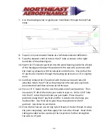
7.
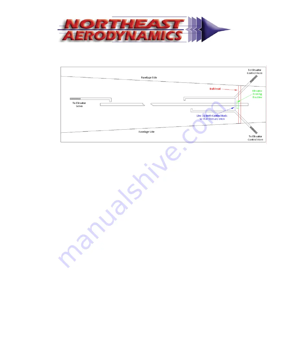
Use
the
drawing
below
to
guide
your
installation
through
the
next
few
steps:
8.
Tape
or
pin
your
elevator
halves
at
a
full
down
‐
elevator
deflection.
9.
Tape
the
elevator
control
rods
to
the
CF
tube
as
shown
in
the
right
‐
hand
side
of
the
above
figure.
10.
Insert
the
CF
elevator
pushrod
into
the
wood
bearing
inside
the
aft
end
of
the
fuselage
and
adjust
the
position
of
the
two
wire
pushrods
until
the
meet
up
properly
with
the
elevator
control
horns.
Ensure
that
the
CF
pushrod
is
inserted
through
the
bearing
by
at
least
a
1/4"
or
slightly
more.
11.
Carefully
remove
the
CF
pushrod
with
the
two
wire
pushrods
still
attached.
Mark
the
CF
rod
at
the
end
where
the
two
wire
pushrods
were
attached
and
then
remove
all
of
the
tape.
12.
Put
a
1/4”
‘L’
‐
bend
into
the
non
‐
threaded
end
of
each
pushrod.
Then
measure
1/4"
aft
of
the
marks
you
made
in
step
11.
Drill
a
1/16”
hole
into
the
CF
rod
at
the
mark
that
you
just
made.
Place
the
wire
pushrods
along
the
CF
pushrod
and
the
‘L’
‐
bends
into
the
holes
you
made
earlier.
Use
thick
CA
to
glue
the
wire
pushrods
to
the
CF
pushrod.
Use
kicker
to
set
the
CA.
13.
Once
the
CA
has
set,
use
strong
nylon
thread,
or
Kevlar
thread,
to
wrap
the
joint
completely,
and
then
apply
thin
CA
to
the
thread.
Heat
shrink
tubing
provided
can
be
used
over
the
CA
joints
to
further
strengthen
the
wire
to
CF
joint.
Summary of Contents for 2M Aquila F3A
Page 25: ... 25 Additional Pictures ...

