6
2. Clearly identify and mark each incoming line with its
respective well (using colored tape and/or numbers).
notE:
Group all vapor lines together and all liquid lines
together for runs through common trenched or walled areas.
Do not mix vapor lines and liquid lines together, even when
individually insulated, as this may contribute to a “short-
circuiting” of heat transfer. Make sure the lines are all marked
and recorded for future reference. The installing contractor
should keep a copy of the location/distances sketch, and
give a second copy to the property owner.
3. Remove the top and front cover of the compressor unit. Pipe
connections, and electrical line access holes, are labeled
on the exterior right hand side of the compressor unit.
• The top two lines go to the air handler.
• The lower two lines go to the borehole.
• Insulate all such exposed hot gas refrigerant tubing with
at least a 220° F rated 3/4 inch thick wall insulation, such
as Armaflex, Rubatex, or Neoprene.
4. Place the compressor unit as close to the air handler as
reasonably possible to limit line set distances. See
line set sizing Between compressor unit &
air handler
For line set sizing between the compressor and air handler
(or other interior heat exchanger), see
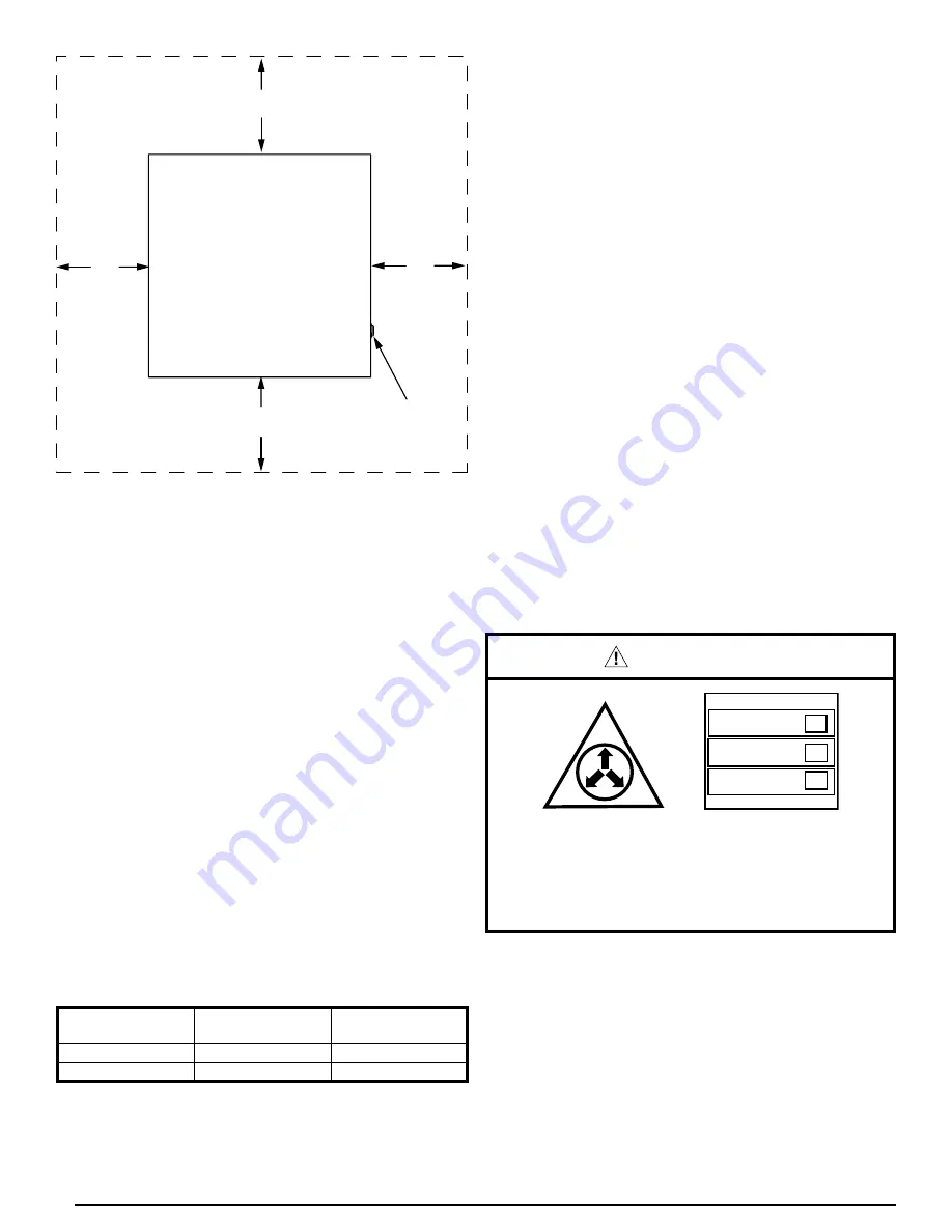
18”
18”
18”
18”
FRONT
REAR
LEFT
SIDE
RIGHT
SIDE
LINESET &
ELECTRICAL
HOOKUPS
GEOTHERMAL
UNIT
NOTE:
Allow 36” clearance from top of unit
Figure 1. service clearances for Interior &
Exterior installations
coMPrEssor
sIzE (Btu)*
lIQuID
lInE
VApor
lInE
24,000 - 36,000
1/2 inch O.D.
3/4 inch O.D.
48,000 - 60,000
1/2 inch O.D.
7/8 inch O.D.
*Compressor size is the actual compressor size in the compressor unit box,
not maximum system capacity, system size, or air handler size.
table 1. line set sizing between the compressor
unit & air handler
Insulating Interior line sets
Insulate all interior refrigerant lines and their connections. The
compressor section contains the expansion valve and the
liquid line is more likely to “sweat” as it condenses moisture
from the interior air.
Use at least a 3/4 inch wall closed-cell insulation that is
non-corrosive to copper to insulate all refrigerant lines. Use
Armaflex, Neoprene, or Rubatex having at least a 220° F
temperature rating for all interior vapor refrigerant lines, and
for all interior liquid refrigerant lines, use Tubolit, Armaflex,
Neoprene, or Rubatex having at least a 180° F liquid refrigerant
temperature rating.
IMPortant notE:
leave an air gap between the insulated vapor refrigerant
line and the insulated liquid refrigerant line wherever
possible. Do not tightly tape or wire tie the insulated lines
together. this will short circuit the heat transfer prior to
the primary heat transfer design areas in the air handler
and in the ground.
use Isolationtype hangers
Isolate the interconnecting refrigerant tubing from the framing
and/or from the duct work, as well as from where refrigerant
tubing runs through stud spaces, enclosed ceilings, or pipe
chases, etc. Use isolation type hangers, since rigid fastening
transmits noise to the structure.
Brazing
Installation of equipment will require brazing operations.
Installer must comply with safety codes and wear appropriate
safety equipment (safety glasses, work gloves, fire extinguisher,
etc.) when performing brazing operations.
WarnInG:
NITROGEN
HEALTH
FLAMMABILITY
REACTIVITY
0 Minimal Hazard
1 Slight Hazard
1
0
0
When purging the system with nitrogen, avoid direct
face exposure or contact with valve when gas is
escaping. always ensure adequate ventilation is
present during the depressurization process. any
uncertainties should be addressed before proceeding.
IMPortant notE:
to prevent internal oxidation and scaling from occuring,
braze all connections with dry nitrogen flowing through
the joints.


