background image

10

Grounding

 WARNING:

The unit cabinet must have an uninterrupted or 

unbroken electrical ground to minimize personal 

injury if an electrical fault should occur. Do not 

use gas piping as an electrical ground!

This unit must be electrically grounded in accordance with 

local codes or, in the absence of local codes, with the National 

Electrical Code (ANSI/NFPA 70) or the CSA C22.1 Electrical 

Code. Use the grounding lug provided in the control box 

for grounding the unit.

Control Board

The control board in the air handler controls the timing 

sequence of the elements. The board is equipped with a 3 

second blower on delay and a 15 second blower off delay 

in heating and a 40 second blower off delay in cooling.

See 

Figure 15 (page 23)

 or 

Figure 16 (page 24)

  and  

Table 9, (page 19 and 20)

 for control board modes and actions.

Twinning

These instructions are to be used when connecting two B64 

air handlers (2-4 ton models) to a common single stage A/C 

condensing unit or heat pump. Twinning is possible for B64 

units with PSC or fixed speed (FSHE) motors. Twinning is 

not possible for units with variable (VSHE) speed motors. 

All low voltage wiring instructions, cautions, and warnings 

accompanying the air handler remain applicable, except for:

Line & Low Voltage Connections

a.  The line voltage connections for both air handlers must 

be the same phase and on the same leg of power.

b. Low voltage wiring should be connected as shown in 

Figure 11 (page 21)

.

c. Wire all other low voltage thermostat terminals to 

both air handlers as shown in 

Figure 10 (page 21)

.  


NOTE: 

If there is any other air moving device in the 

duct work, consult the factory for a resolution.

Heater Kits

When electric heat packages with circuit breakers are field-

installed, the circuit breaker may be used as a disconnecting 

means in most applications. Reference the NEC and local 

codes for disconnect requirements.
If a heater kit is installed:

B64EM and B64VM air handlers are shipped from the factory 

without an electric heater kit installed. If electric heat is 

desired, a heater kit may be purchased separately and field 

installed. Determine the correct size heater kit for your unit 

by referring to the heater kit installation instructions.
1. Connect the 2 wire plug of the air handler to the mating 

2 wire plug of the heater kit.

2. Connect the line voltage leads to the circuit breaker or 

terminal block provided.

3. Connect the heater kit plug with the mating receptacle 

on the air handler control board.

4. Refer to Heater Kit Installation Instructions to determine 

if you need to replace a limit or add an air baffle.

5. Connect blue blower limit wires according to Heater Kit 

Installation Instructions and the corresponding Wiring 
Diagram.

If a heater kit is not installed:

1. Remove the 2 wire plug of the air handler by cutting the 

wires and discarding the plug.

2. Strip the ends of the 2 air handler wires and connect to 

the line-voltage leads with the 2 wire nuts provided.

3. Certain air handler models are equipped with blower 

limits as shown in 

Figure 15 (page 23)

These are left 

unconnected if a heater kit is not installed. 

Humidifier

The unit has an output to power a humidifier when the blower 

is running. This output is rated to 1.0 amp at 208/240V.

Dehumidification Options

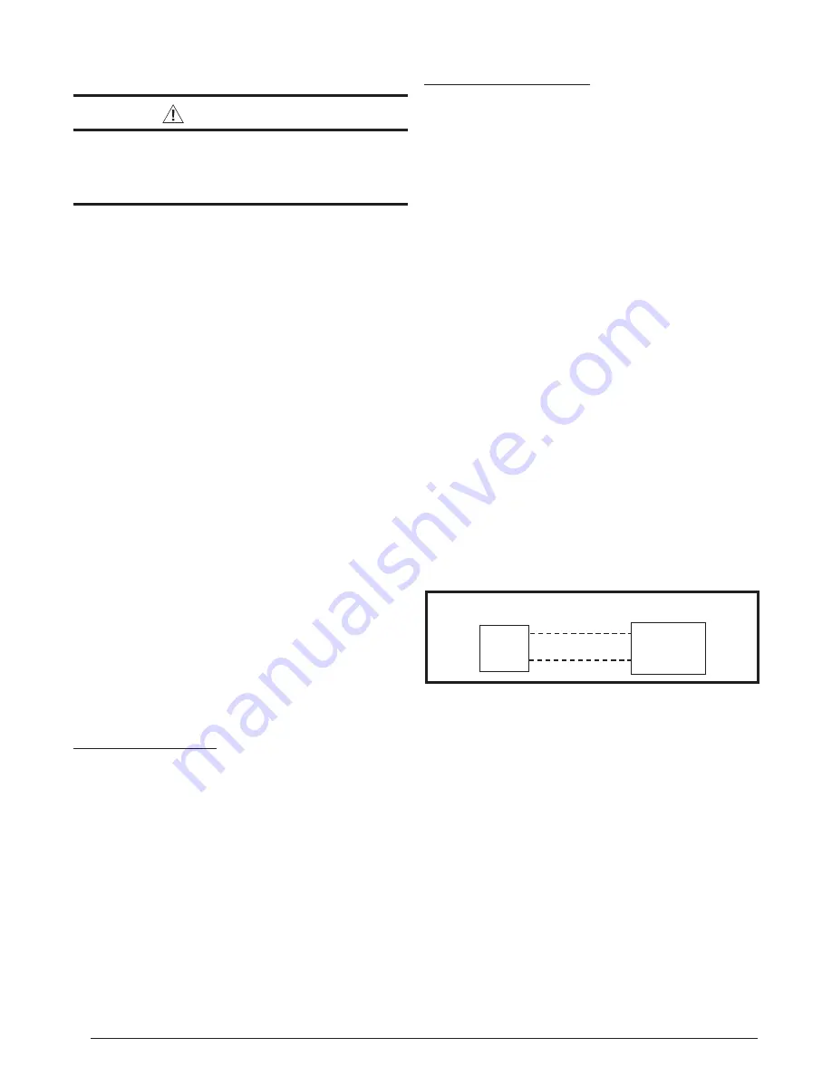
The motor control board has a 

DHUM 

or 

D

 connection that 

allows the system to increase the amount of humidity that 

is removed from the circulating air. See 

Figure 14

 & 

Figure 

15 (page 23)

 This is accomplished by reducing the CFM 

and allowing the cooling coil to become colder. This will 

only occur when there is a call for cooling. There are many 

ways that this can be electrically wired.
1. If the room thermostat incorporates a humidity sensor and 

DHUM

 output, connect the 

DHUM

 on the thermostat to 

the 

D

 terminal on the motor control board. See 

Figure 7

.

2. If using a separate humidistat, connect the 

DHUM

 & 

R


terminals on the humidistat to the 

D

 & 

R

 terminals on 

the motor control board of the air handler. In this option, 

the 

DHUM

 output of the humidistat must be set so it is 

only closed when there is a call for dehumidification.

3. If a humidistat is not available, it is an acceptable 

option to connect the 

R

 & 

terminals on the motor 

control board together with a field supplied wire. This 

option causes the blower to run at a reduced CFM for 

10 minutes after a call for cooling. 

NOTE:

 If outdoor 

unit is a heat pump, connect the

 O 

terminal to the 

D


terminal.

Electronic Air Cleaner (EAC)

The unit has an output to power an electronic air cleaner 

when the blower is running. This output is rated to 1.0 amp at 

208/240V. See 

Figure 13 (page 22) 

and 

Figure 14 (page 23)

.

STARTUP & ADJUSTMENTS

Before You Start the Unit

Prior to start-up, complete the following inspections:

  Verify the unit is level and properly located with adequate 

clearances for servicing the unit as shown in 

Table 1, 

  (page 4)

.

  Check condensate drain line(s) for proper drainage.

  Verify the surrounding area and top of the unit is free from 

obstructions and debris.

 Check all duct connections. Make sure the duct work is 

adequately sealed to prevent air leakage.

  Check all coil connections for leaks.

 Verify that the line voltage power leads are securely 

connected and the unit is properly grounded. Make sure 

all doors are installed before restoring power to the unit

DHUM

R

R

DHUM

HUMIDISTAT

MOTOR

CONTROL BOARD

Figure 7. DHUM Wiring Configuration

Summary of Contents for B64EM Series

Page 1: ...well Pay attention to all safety warnings and any other special notes highlighted in the manual Improper installation of the furnace or failure to follow safety warnings could result in serious injury...

Page 2: ...wer Continuously 11 Selecting Continuous Low Speed Fan Operation 11 Turning the Blower Off 11 System Cooling 11 System Heating 11 Selecting Minimum Electric Heat Airflow 11 Blower Configurations 11 De...

Page 3: ...ation service and operation of this unit Unqualified individuals should not attempt to interpret these instructions or install this equipment Failure to follow safety recommendations could result in p...

Page 4: ...ment Refer to applicable building codes for details Static pressure drop through louvered openings and through return air plenums should be considered in the overallductdesigninthedeterminationoftheto...

Page 5: ...needed gaskets and grommets around penetrations into the air handler such as for electrical wiring AIR HANDLER INSTALLATION B64 series air handlers are shipped ready for vertical upflow installation a...

Page 6: ...Right Installations 1 Remove the coil access door Unscrew the line set tube close off plate from the front left cabinet rail 2 Slide the coil and drain pan assembly out of the unit 3 Remove the sheet...

Page 7: ...ntact with valve when gas is escaping Always ensure adequate ventilation is present during the depressurization process Address any uncertainties before proceeding Failure to comply with this warning...

Page 8: ...ondensables to prevent low efficiency operation or damage to the unit The suggested range of evacuation is 350 500 microns 9 Charge the system with refrigerant Refer to the outdoor unitinstallationman...

Page 9: ...ation service and operation of this unit Unqualified individuals should not attempt to interpret these instructions or install this equipment Failure to follow safety recommendations could result in p...

Page 10: ...5 Connect blue blower limit wires according to Heater Kit Installation Instructions and the corresponding Wiring Diagram If a heater kit is not installed 1 Remove the 2 wire plug of the air handler b...

Page 11: ...n B64EM models B64VM models automatically set the heating speed based on the amount of installed heat The A B switch must be set appropriately for the unit cabinet size For C sized cabinets the A B sw...

Page 12: ...cted airflow while the system is in the lo cool mode and 100 of the selected airflow while in hi cool mode Units with an FSHE control scheme B64EM have a control board that includes a 7 segment displa...

Page 13: ...or on the blower and motor as part of the annual inspection Blower Fan Wheel Inspect the blower wheel blades for accumulations of dirt and clean if necessary Inspect mounting nut for tightness when do...

Page 14: ...typ 13 4 K O typ 1 7 8 3 5 8 5 5 8 DETAIL D 3 1 4 2 1 4 15 1 4 13 SUCTION LIQUID W 1 1 8 1 7 8 7 8 K O H 22 A CABINET SIZE H W A DETAIL D A 43 5 16 14 3 16 12 3 4 No B 43 5 16 19 11 16 18 1 4 No Tall...

Page 15: ...l Drain Pan Coil Assembly Motor Mount Kit Blower Motor Transformer Capacitor Circuit Breaker 60A Heating Element Assembly Filter Tracks Blower Wheel Blower Housing Motor Control Board Filter Door Uppe...

Page 16: ...0 795 720 685 0 1 1 0 1095 1040 995 950 900 850 805 750 1 1 1 0 1155 1105 1060 1010 965 920 870 825 0 0 0 1 1230 1185 1140 1090 1045 1010 965 920 1 0 0 1 1285 1260 1210 1165 1125 1080 1040 1010 0 1 0...

Page 17: ...TON 560 560 1200 3 5 TON 600 600 1250 625 650 2 TON 1300 4 TON 700 2 TON 700 1350 750 750 1400 800 2 5 TON 800 2 5 TON 1450 850 850 1500 875 875 1550 890 950 1600 5 TON 930 1050 3 TON 1650 950 1150 3...

Page 18: ...ING 0 OFF 1 ON AIRFLOW CFM 5 6 7 8 0 0 0 0 1100 0 0 0 1 1200 0 0 1 0 1250 0 0 1 1 1300 0 1 0 0 1350 0 1 0 1 1400 0 1 1 0 1450 0 1 1 1 1500 1 0 0 0 1550 1 0 0 1 1600 1 0 1 0 1650 1 0 1 1 1700 1 1 0 0 1...

Page 19: ...W1 W2 EHEAT ON 5 KW Stage 1 Heat on instantly Heat blower on after 3 second delay 8 KW 10 KW Stage 1 Heat on instantly Heat blower on after 3 second delay Stage 2 Heat on after 5 seconds delay 15 KW...

Page 20: ...fter 5 seconds delay 15 KW Stage 1 Heat on instantly Cool blower on after 3 second delay Stage 2 Heat on after 5 seconds delay Stage 3 Heat on after 30 seconds delay 20 KW Stage 1 Heat on instantly Co...

Page 21: ...cal Heat Pump with 2 Stage Air Handler G R W2 C O Y1 Thermostat O Y1 R C G R W E Thermostat Y1 C Y1 W2 Typical 2 Stage Air Conditioner with 2 Stage Air Handler Typical 2 Stage Heat Pump with 2 Stage A...

Page 22: ...1 BLWDTC BLWDTC_R HEAT COOL EAC L 1 L 2 P2 R C G W Y 3A Fuse HEATER P1 Figure 12 Single Stage Control Board C R G Y2 Y O 1W 2W 1Y L LED 1 HEATER P1 L 2 HUM EAC P2 3A Fuse P3 Figure 13 Two Stage Contro...

Page 23: ...R ECM BLOWER Figure 14 Fixed Speed Motor Control Board GND SENSOR DEHUM Y1 H L2 OUT L2 IN L1 IN L1 OUT Y1 Y Y2 W C EXPANSION PORT R RED GREEN TEST PORT BLOWER MOTOR RED INPUTS COOL HEAT FAN SPEED OUTP...

Page 24: ...entation avant l entretien 3 Le transformateur peut avoir un robinet principal double tension Agencez la position du robinet au type de tension de l installation 4 Si le c blage interne est remplac ut...

Page 25: ...e tension Agencez la position du robinet au type de tension de l installation 4 Si le c blage interne est remplac utilisez seulement un fil de cuivre 105 C du m me gabarit WIRING DIAGRAM CONNECT TO W1...

Page 26: ...tterthanyourcustomer This includes being able to install the product according to strict safety guidelines and instructing the customer on how to operate and maintain the equipment for the life of the...

Page 27: ...27...

Page 28: ...10436960 NEW Specifications illustrations subject to change without notice or incurring obligations 08 22 O Fallon MO Nortek Global HVAC LLC 2022 All Rights Reserved...

Reviews: