J10
Install J10 for
On/Off
control only
Capacity
adjust
High Water
P8
K2
K3
P4
P5
P6
Status
Lamps
240/208/120
VA
C
24
V
A
C
1.5 Amps
G
Y
Cylinder
Fill
V
Drain
V
1
2
3 4
8
9 19 20
24
V
A
C
Security
Loop
Control
Ground
(-)
Control
Signal
(+)
24
V
A
C
Fan
Security
Fan
Start
(+)
Fan
Start
(--)
208
240
L1
External
Internal
120 P
On/Off/Drain
Switch
Transformer
208
240
L1
120 P
208
240
L1
120 P
S
Note:
Install jumper
from P to
terminal
corresponding
to mains
voltage.
Note:
Room Steam Distributor
not included with RH
Duct humidifier
Hot
Neutral
Ground
Hot
Hot
Ground
Hot
Hot
Ground
120 VAC
208 VAC
240 VAC
M
ROOM Steam Distributor
TB2
TB1
+
_
~
~
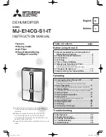
Rh Humidifier 120/208/240 Vac
INTERNAL WIRING DIAGRAM
DIAGRAM No. 2548760
REV. B DATE: Sept. 9, 2009
P1
P2
P3
P7
RH Wiring Diagram
51
| Troubleshooting
Figure 36: RH Wiring Diagram
Summary of Contents for RH
Page 7: ...Introduction 4 ...
Page 9: ...Installation 6 Typical RH Installation Figure 3 Typical Humidifier Installation ...
Page 20: ...17 Installation Modulating Control Wiring Figure 18 Modulating Controls ...
Page 21: ...Installation 18 Figure 19 Modulating Control Wiring Figure 20 Duct Sensor Wiring ...
Page 31: ...Start Up 28 ...
Page 36: ...33 Operation Humidifier Schematic Figure 28 Humidifier Schematic ...
Page 55: ...Spare Parts 52 Exploded View and Spare Parts List ...
Page 56: ...53 Spare Parts RH Spare Parts Figure 37 RH Spare parts ...
Page 58: ...55 Warranty ...