background image

65

Installation

Nortec GS

2583703_EN_1608

5.11.5  Electrical Connections Checklist

Check the following to ensure that the electrical connections for the humidifier have been installed correctly:


…

Power supply meet the rated current draw limits shown on the specification label (

Figure 3 on page 10

)?


…

Power supply have an external dedicated fused disconnect switch?


…

All wiring done according to the wiring diagram and instructions in this manual?


…

M

ain power cable proper grounding through the ground lug inside the electric cabinet?


…

All cables fastened securely?


…

All cables free of tension and pass through cable glands or grommets?


…

Electrical installation meet the applicable national and local codes?


…

All access panels closed and fastened securely?

Summary of Contents for GS

Page 1: ...INSTALLATION MANUAL Gas fired Steam Humidifier Nortec GS 2583703_EN_1608 Humidification and Evaporative Cooling IMPORTANT Read and save these instructions This manual to be left with the equipment ...

Page 2: ... use gasoline or other flammable va pors and liquids in the vicinity of this or any other appliance WHAT TO DO IF YOU SMELL GAS DO NOT try to light any appliance DO NOT touch any electrical switch DO NOT use any phone in the building Immediately call your gas supplier from a neighbor s phone Follow the gas supplier s instructions If you cannot reach your gas supplier call the fire department ...

Page 3: ...INSTALLATION MANUAL Gas fired Steam Humidifier Nortec GS 2583703_EN_1608 ...

Page 4: ...u ment nor the information contained herein shall be reproduced used or disclosed to others without the written authorization of Nortec Humidity Ltd except to the extent required for installation operation or maintenance of the customer s equipment Liability Notice Nortec Humidity Ltd does not accept any liability due to incorrect installation maintenance or operation of the equipment or due to th...

Page 5: ...act Unit Only 22 5 4 3 Standard Floor Stand Mounting Compact Unit Only 24 5 4 4 Standard Mounting Full Size Unit 26 5 4 5 Optional Stand Mounting Full Size Unit 27 5 4 6 Mounting Checklist 28 5 5 Steam Connection 29 5 5 1 Installing the Main Steam Pipe 29 5 5 2 Best Practices for Installing Steam and Condensate Lines 30 5 5 2 1 Common Steam and Condensate Line Installation Mistakes 33 5 5 3 Steam ...

Page 6: ... Control Signal Inputs 54 5 11 Electrical Connections 55 5 11 1 General 55 5 11 2 Wiring Diagrams 56 5 11 2 1 Nortec GS 50 100 150 200 300 56 5 11 2 2 Nortec GS 450 600 57 5 11 3 External Connections 58 5 11 3 1 External Security Loop 58 5 11 3 2 Modulating Demand or Humidity Signal 59 5 11 3 3 On Off Humidistat Signal 60 5 11 3 4 Full Tank Blowdown Signal Connection 60 5 11 3 5 Remote Fault PCB C...

Page 7: ...ons and accessories may only be described in so far as is necessary for proper installation and operation of the equipment Additional information on available options and accessories can be obtained in the instructions that are supplied with them This manual is restricted to the installation of the Nortec GS humidifier and is intended for well trained personnel who are suitably qualified for their...

Page 8: ...priate cross references to these publications have been added in this manual Storage of Manual Keep this manual in a place where it is safe and readily accessible If the equipment is moved to another location make sure that the manual is passed on to the new user If the manual is lost or misplaced contact your Nortec representative for a replacement copy Language Versions This manual is also avail...

Page 9: ...umidifier must be familiar with and comply with the appropri ate regulations on workplace safety and prevention of accidents Intended Use The Nortec GS humidifier is intended exclusively for air humidification using a Nortec approved steam distributor within specified operating conditions refer to the Operation and Maintenance Manual for details Any other type of application without the express wr...

Page 10: ...in the building Leave the building immediately Call your gas supplier immediately from a location far away from the building with the gas leak Follow the gas supplier s instructions If you cannot reach your gas supplier call the fire department WARNING Risk of severe burns from contact with hot steam vapors The Nortec GS humidifier produces hot steam vapors for humidification Bare skin in contact ...

Page 11: ...of the various safety labels on the Nortec GS humidifier is shown in Figure 1 Figure 1 1 2 3 4 5 Safety Labels 1 Label gas safety warning 2 Label keep cabinet closed warning 3 Label installation guidelines 4 Label general safety warning 5 Label specification ...

Page 12: ...6 For Your Safety 2583703_EN_1608 Nortec GS This page intentionally left blank ...

Page 13: ...mage If parts components are damaged notify the shipping company immediately Verify the model type on the specification label to ensure that it is suitable for your installation Refer to Figure 3 on page 10 3 2 Storage and Transportation Storage Store the Nortec GS humidifier in its original packaging inside a protected area that meets the follow ing requirements until it is installed These requir...

Page 14: ...8 Receiving and Storage 2583703_EN_1608 Nortec GS This page intentionally left blank ...
Page 15: ... ultra low NOx condensing NX and standard efficiency models in capacities rang ing from 50 lb h 23 kg h to 600 lb h 260 kg h The CS and NX models are classified as Category IV appliances The Nortec GS humidifier comes in two housing styles compact 50 100 lb h 23 45 kg h and full size 150 600 lb h 65 260 kg h Refer to Figure 2 Figure 2 1 2 3 4 5 Nortec GS Series Humidifiers 1 GS 50 100 compact hous...

Page 16: ...mber serial number and ratings refer to Figure 3 Figure 3 Nortec GS Humidifier Specification Label The breakdown of the model number is shown in Figure 4 Figure 4 Nortec GS 150 CS Series Gas Steam Capacity lb h 50 100 150 200 300 450 600 Efficiency CS Condensing High Efficiency NX Condensing Ultra Low NOx Standard Efficiency Model Number Breakdown Example ...

Page 17: ...0 01 2 5 Minimum 24 800 7 3 20 9 0 01 2 5 Model GS 150 CS Natural gas Maximum 186 000 54 5 150 68 0 01 2 5 Minimum 37 200 10 9 30 13 6 0 01 2 5 Propane Maximum 186 000 54 5 150 68 0 01 2 5 Minimum 37 200 10 9 30 13 6 0 01 2 5 Model GS 200 CS Natural gas Maximum 248 000 72 7 200 91 0 01 2 5 Minimum 24 800 7 3 20 9 0 01 2 5 Propane Maximum 248 000 72 7 200 91 0 01 2 5 Minimum 24 800 7 3 20 9 0 01 2 ...

Page 18: ...30 000 38 1 100 45 0 01 2 5 Minimum 26 000 7 6 20 9 0 01 2 5 Model GS 150 NX Natural gas Maximum 195 000 57 1 150 68 0 01 2 5 Minimum 39 000 11 4 30 13 6 0 01 2 5 Model GS 200 NX Natural gas Maximum 260 000 76 2 200 91 0 01 2 5 Minimum 26 000 7 6 20 9 0 01 2 5 Model GS 300 NX Natural gas Maximum 390 000 114 3 300 136 0 01 2 5 Minimum 39 000 11 4 30 13 6 0 01 2 5 Model GS 450 NX Natural gas Maximum...

Page 19: ...e steam distribution manifold and mini SAM e Steam distribution system for use in an air duct where reduced absorption distance is re quired Blower pack remote mounted For direct room humidification or use in conditioned spaces without a built in air distribution system The Nortec GS 50 100 model can use a remote mounted blower pack for steam distribution blower pack ordered as an accessory Digita...

Page 20: ...14 Product Overview 2583703_EN_1608 Nortec GS This page intentionally left blank ...

Page 21: ...s a gas fired humidifier Improper installation adjustment alteration service maintenance or use can cause carbon monoxide poisoning explosion fire or other hazards that can cause serious injury death or property damage If assistance is required contact a qualified installer service agency or your local gas supplier Use only factory authorized and listed kits or accessories when installing or modif...

Page 22: ...limit external security loop 6 Drain line condensate with trap 7 Funnel air gap with optional trap 8 Inlet water 9 Outlet condensate drain 10 Outlet drain 11 Inlet intake air 12 Inlet gas 13 Supply line water 14 Trap sediment 15 Supply line gas 16 Valve manual gas shutoff 17 Switch disconnect electrical fused dedicated 18 Fitting union 19 Valve water shutoff 20 Filter water optional but recommende...

Page 23: ...t supply air 5 Humidistat On Off high limit external security loop 6 Drain line condensate with trap 7 Funnel air gap with optional trap 8 Supply line gas 9 Manual gas shutoff valve 10 Fitting union 11 Trap sediment 12 Filter water optional but recommended 13 Valve water shutoff 14 Supply line water 15 Fitting union 16 Switch disconnect electrical fused dedicated 17 Drain line 18 Drain line exhaus...

Page 24: ...nd temperatures of 140 158 F 60 70 C that can be generated during operation of the humidifier Care must also be taken to ensure that the unit is not mounted above sensitive equipment or walkways Do not mount the humidifier on wooden floors carpeting or near combustible materials Adhere to all local and national installation codes Do not mount the humidifier on vibrating surfaces or near hot surfac...

Page 25: ...fier is to be installed must permit routing of exhaust air to the outside Adhere to all local and national installation regulations For additional requirements for the different types of exhaust vent installations refer to Exhaust Vent Connection on page 43 Gas Supply Gas supply to the unit must be equipped with a certified manual gas shutoff valve located in the immediate vicinity of the humidifi...

Page 26: ...t exceed the maximum current draw of 15 A 5 4 Mounting the Humidifier Before mounting the Nortec GS humidifier refer to Site Requirements on page 18 for the location and mounting requirements 5 4 1 Clearances The required clearances are listed in Table 9 on page 21 and the suggested clearances are listed in Table 10 on page 21 Refer to Figure 7 Consult local and national installation regulations N...

Page 27: ...2 mm 0 in 0 mm 36 in 914 mm 0 in 0 mm 0 in 0 mm GS 200 36 in 914 mm 30 in 762 mm 0 in 0 mm 36 in 914 mm 0 in 0 mm 0 in 0 mm GS 300 36 in 914 mm 30 in 762 mm 0 in 0 mm 36 in 914 mm 0 in 0 mm 0 in 0 mm GS 450 36 in 914 mm 30 in 762 mm 0 in 0 mm 36 in 914 mm 30 in 762 mm 0 in 0 mm GS 600 36 in 914 mm 30 in 762 mm 0 in 0 mm 36 in 914 mm 30 in 762 mm 0 in 0 mm 5 4 1 1 Overall Dimensions and Weight The ...

Page 28: ... washer not supplied Use longer bolt if going through drywall or other structural material into the mounting surface 7 Level the mounting bracket and mark the locations of the remaining three attachment points 8 Install three more 3 8 in lag bolts and washers not supplied and secure the mounting bracket to the mounting surface 9 Remove the door panels from the humidifier 10 Remove and discard the ...

Page 29: ...Mounting Compact Unit Only 1 Bracket mounting supplied 2 Washer flat 3 8 in 4 not supplied 3 Bolt lag 3 8 2 in 4 not supplied 4 Bolt M6 12 4 supplied 5 Washer flat M6 4 supplied 6 Washer flat 1 4 in 2 not supplied 7 Bolt lag 1 4 1 in 2 not supplied 8 Screw sheetmetal 4 supplied 9 Bracket L 2 supplied 10 Screw shipping 2 discard ...

Page 30: ... feet Note If desired remove the leveling screws and secure the floor stand to the floor with 3 8 in bolts and washers not supplied 5 Remove the door panels from the humidifier 6 Remove and discard the two shipping screws that secure the unit to the shipping pallet WARNING Heavy object risk of personal injury or damage to equipment Prevention Use an appropriate lifting device to lift the humidifie...

Page 31: ...ng Compact Unit Only 1 Nut 2 Nut jam 3 Screw leveling 4 Bolt M6 12 4 supplied 5 Washer flat M6 4 supplied 6 Stand floor 7 Bolt lag 1 4 1 in 2 not supplied 8 Washer flat 1 4 in 2 not supplied 9 Bracket L 2 supplied used if unit is installed against a vertical mounting surface 10 Screw sheetmetal 4 supplied 11 Screw shipping 2 discard ...

Page 32: ...ject risk of personal injury or damage to equipment Prevention Use an appropriate lifting device to lift the humidifier Lift the unit from the bottom and not the side or top panels 3 Carefully lift the humidifier by its base frame and raise it off the shipping pallet Lower it onto a hard level floor 4 Add shims under the frame brackets if necessary to level the unit Note If desired secure the unit...

Page 33: ... the instructions in the accessory box 4 Set the mounting stand on a hard level floor and level it using shims if necessary Note If desired secure the mounting stand to the floor with 3 8 in bolts and washers not supplied WARNING Heavy object risk of personal injury or damage to equipment Prevention Use an appropriate lifting device to lift the humidifier Lift the unit from the bottom and not the ...

Page 34: ...ensure that the humidifier has been mounted correctly Unit installed in the correct location according to Clearances on page 20 Adequate clearance for servicing unit Mounting surface stable and capable of supporting the full operating weight of the humidifier Unit level Unit secured properly ...

Page 35: ...team Pipe Figure 12 2 5 6 4 min 2 o min 10 o min 10o 6 5 min 12 in 300 mm 1 3 min 12 in 300 mm Main Steam Line Installation 1 Steam outlet humidifier 2 Clamp gear supplied 3 Steam pipe rigid main must rise straight up minimum 12 in 300 mm above steam outlet before continuing to steam distributor Refer to Table 12 on page 30 for maximum equivalent length of steam line 4 Cuff hose supplied 5 Steam h...

Page 36: ... size units Refer also to Table 13 on page 31 for equivalent length of typical steam line fittings IMPORTANT When calculating the backpressure on the unit include allowance of approxi mately 0 12 in H2O for every foot 100 Pa for every meter of steam line and every 90 elbow Use long radius elbows for steam pipes This minimizes backpressure and formation of condensation IMPORTANT When determining th...

Page 37: ...on excess backpressure also affects performance of the unit Prevention Observe the following Upon completion of the installation purge the steam line to remove any contaminants and installation materials The steam hose if used must not have any kinks or other restrictions To prevent condensate pockets the steam line must not sag If necessary support the steam line with pipe clamps trough or wall b...

Page 38: ... horizontal to vertical transitions in the steam line The condensate drain lines should always connect to full size Tee connectors in the steam line Refer to Figure 13 on page 31 The condensate lines must have a minimum downslope of 1 2 with a minimum 12 in 300 mm diameter condensate trap and connect to the building floor drain with condensate cooler if required The condensate trap must be at leas...

Page 39: ... Mistakes 1 The condensate trap is located less than the required minimum 12 in 300 mm below the steam distributor 2 No condensate trap is installed at the horizontal to vertical transition 3 The steam line does not run straight up for the required minimum 12 in 300 mm before continuing on to the steam distributor 4 Steam line is not sloped upslope minimum 10 downslope minimum 2 is not maintained ...

Page 40: ...uce in diameter except at the steam distributor and condensate line installed just before the restriction Steam lines do not merge except at the steam distributor through a Nortec adaptor Steam line does not sag Steam connections secured with clamps Clamps torqued adequately Allowances made for thermal expansion of rigid pipes and shrinkages of steam hose Steam line insulated over its entire lengt...

Page 41: ... 15 1 2 3 4 5 6 7 Water Supply and Drain Connections Compact Unit 1 Inlet fill valve 3 4 in BSPP plastic thread 2 Adaptor 3 4 in BSPP to 1 2 in NPT supplied 3 Supply line water minimum 1 2 in 13 mm diameter 4 Funnel air gap should be minimum 2 1 2 in 64 mm in diameter and drain pipe connected to it should be have minimum diameter of 1 1 2 in 38 mm 5 Hose drain 7 8 in 22 mm I D not supplied minimum...

Page 42: ...or 3 4 in BSPP to 1 2 in NPT supplied 3 Supply line water minimum 1 2 in 13 mm diameter 4 Outlet drain 7 8 in 23 mm O D unthreaded 5 Clamp hose not supplied 6 Hose drain 7 8 in 23 mm I D not supplied minimum downslope of 1 2 and must not touch sides or bottom of funnel 7 Funnel air gap should be minimum 2 1 2 in 64 mm in diameter and drain pipe connected to it should have minimum diameter of 1 1 2...

Page 43: ...ensate compact unit not supplied must have minimum downslope of 1 2 and must not touch sides or bottom of funnel Use Nortec condensate hose 3 Funnel air gap funnel must be located below the condensate outlet 4 Outlet condensate drain full size unit 1 2 in 13 mm O D unthreaded 5 Hose drain exhaust condensate full size unit not supplied must have minimum downslope of 1 2 and must not touch sides or ...

Page 44: ... away from the control cabinet to keep any rising steam from damaging the electrical components in the control cabinet The diameter of the air gap funnel should be minimum 2 1 2 in 64 mm The drain pipe connecting the air gap funnel to the building drain should have a minimum inner diameter of 1 1 2 in 38 mm Use stainless steel minimum DIN 1 4301 or copper pipe The drain hose from the humidifier sh...

Page 45: ...urge protected and pressure regulated to 30 80 psig 207 550 kPa Check for leaks in the water supply line Air gap funnel in the floor located away from the control cabinet in the humidifier Air gap funnel minimum 2 1 2 in 64 mm in diameter Drain pipe between air gap funnel and building drain have a minimum internal diameter of 1 1 2 in 38 mm Copper or stainless steel pipe Drain hose from humidifier...

Page 46: ...ir Installation This type of installation draws combustion air from inside the room space where the humidifier is installed Refer to Table 14 for the required minimum cross sectional area for the fresh air intake in the room space An appropriate opening to the outside of the building must be provided to allow fresh combustion air into the space Adhere to all local and national installation regulat...

Page 47: ...quirements on page 42 Table 15 Air Intake Vent Diameter Model Intake Vent Diameter GS 50 2 in 50 mm GS 100 GS 150 3 in 75 mm GS 200 GS 300 4 in 100 mm GS 450 GS 600 6 in 150 mm Figure 19 shows the sealed combustion connection for the compact and full size Nortec GS humidifiers Figure 19 1 2 4 5 6 3 ft 1m minimum 2 3 Nortec GS Sealed Combustion Connection 1 Terminal air intake elbow terminal locate...

Page 48: ...e air intake terminal and exhaust vent terminal must be located on an exterior surface The location and spacing between the terminals must comply with all local and national regulations with at least a minimum spacing of 3 ft 1 m between them At low temperatures water condensation can occur on the outside of the air intake vent To prevent this Nortec suggests adding in line heating and insulation ...

Page 49: ...e than six elbows in the system All horizontal exhaust vent runs must maintain a constant minimum upslope of 2 to prevent ac cumulation of condensate When an exhaust vent run exceeds 20 ft 6 1 m insulate the exhaust vent pipe to reduce the amount of condensate that could form in the flue gases When an exhaust vent passes through a cold area or a location that has large amounts of air flow over the...

Page 50: ...0 CS NX 3 in 80 mm BH or CPVC GS 150 CS NX 3 in 80 mm BH or CPVC GS 200 CS NX 4 in 100 mm BH or CPVC GS 300 CS NX 4 in 100 mm BH or CPVC GS 450 CS NX 6 in 150 mm BH or CPVC GS 600 CS NX 6 in 150 mm BH or CPVC The exhaust outlet on the unit has a female connection metric Each unit is supplied with a metric to imperial adaptor with internal seals to accomodate imperial vent sizes Figure 20 on page 4...

Page 51: ...ointed down for optional sealed combustion hookup outside 7 Drain condensate with trap minimum 12 in 300 mm trap height and connected to floor drain or condensate pump 8 Inlet air intake 9 Outlet exhaust 10 Vent air intake for optional sealed combustion horizontal hookup 11 Vent exhaust BH type plastic or stainless steel All joints air and water tight Short horizontal run with slope as shown recom...

Page 52: ...pointed down for optional sealed combustion hookup 3 Outlet exhaust outlet 4 Inlet air intake 5 Vent air intake for optional sealed combustion horizontal hookup 6 Drain condensate with trap minimum 12 in 300 mm trap height and connected to floor drain or condensate pump 7 Tee condensate 8 Hanger 9 Vent exhaust BH type plastic or stainless steel All joints air and water tight Full condensate Tee wi...

Page 53: ...th a metric to imperial adaptor with internal gaskets to accomodate imperial vent sizes To connect the exhaust vent first insert the adaptor into the exhaust outlet and secure it to the top panel with four sheetmetal screws supplied refer to Figure 22 Then slide the exhaust vent into the adaptor until it bottoms out and secure it with the clamp built into the adaptor A sealant is not required Make...

Page 54: ...r power assist appliance The exhaust vent must not share a chimney flue servicing an appliance designed to burn solid fuel All joints must be sealed using a sealant recommended by the vent manufacturer The exhaust vent must have a minimum equivalent length of 10 ft 3 m and must not exceed an equivalent length of 100 ft 30 m except for the Nortec GS 50 using propane gas which is limited to 50 ft 15...

Page 55: ...ailingwinds Avoid areas where experience shows that condensate drip may cause problems such as above planters patios or over public walkways or over an area where condensate or vapor could create a nuisance or hazard or could be detrimental to the operation of regulators relief valves or other equipment Refer to the vent manufacturer s installation instructions The vent terminal must be installed ...

Page 56: ...Requirements on page 51 IMPORTANT Tampering with the gas valve without the express consent of Nortec will void the warranty 5 9 1 Gas Connection Compact and Full Size Unit Figure 23 1 2 3 4 4 2 7 3 5 5 6 Gas Connection 1 Inlet gas NPT female full size unit see note below 2 Fitting union not supplied 3 Valve manual gas shutoff not supplied 4 Trap sediment not supplied 5 Stainless steel section of g...

Page 57: ...A flexible sealant suitable for use with natural gas and propane gas is recommended All gas piping must be adequately supported to prevent any strain on the humidifier gas connection Upon completion of the gas installation perform the Gas Leakage Test described below 5 9 3 Gas Leakage Test DANGER Risk of explosion and fire Prevention NEVER use an open flame to check for gas leaks Risk of injury de...

Page 58: ...s shutoff valve installed immediately upstream from the humidifier Sediment trap installed if using black pipe Stainless steel section of pipe installed at the gas connection to the humidifier Gas pipe routing allow clear access to other service connections at humidifier Gas piping adequately supported Gas leakage test completed and all leaks fixed De pressurize gas supply line after leak test ...

Page 59: ...w or lack thereof Locate the high limit humidistat downstream of the humidifier s distributor so that it can sense a duct that is over humidified Recommended setting is 85 RH Locate it downstream of the distribu tor at least 5x the absorption distance away If the absorption distance is not known locate it at least 10 feet 3 m downstream from the distributor Can be a humidistat modulating or On Off...

Page 60: ...ntrol Signals Humidity Control with Internal PI Controller Humidity Sensor Signals Digital Inputs via Modbus BACnet IP MSTP slave 0 5 VDC potentiometer 135 10kΩ 1 5 VDC 0 10 VDC 2 10 VDC 0 20 VDC 0 16 VDC 3 2 16 VDC 0 20 mA 4 20 mA 0 5 VDC potentiometer 135 10kΩ 1 5 VDC 0 10 VDC 2 10 VDC 0 20 VDC 0 16 VDC 3 2 16 VDC 0 20 mA 4 20 mA BACnet IP BACnet MSTP Slave Modbus Lonworks Option BACnet MSTP BTL...

Page 61: ...ention Take appropriate measures to protect the electronic components inside the unit against damage caused by electrostatic discharge ESD Refer to ANSI ESD S20 20 All electrical installation work must be performed only by a licensed electrician authorized by the customer It is the customer s responsibility to verify qualifications of the personnel The electrical installation must be performed acc...

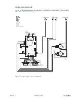
Page 62: ...o Pump1 Micro Pump2 R Y Gr Y R Bk Bk R Gr W 2 Burner Units Only 2 Burner Units Only J2 J5 J15 J16 J14 J1 J10 J3 J7 J8 J17 J11 J9 J12 J6 J13 float pwm1 pwm2 fill 1 2 3 ext ntc power a p ignition1 ignition2 RS485 2 RS485 1 24Vout pmp_fre drn_blower digi inputs DRIVER BOARD 1 R J1 J2 PUMP MODULE CS NX Models on Driver Board J18 COM Remote Fault PCB NO NC Steam Unit ON Error Service COM NO NC COM NO C...

Page 63: ...ower digi inputs DRIVER BOARD 2 R J1 J2 PUMP MODULE CS NX Models on Driver Board J18 Gas Valve3 Gnd TH V2 V1 Ignition Module 3 Gnd TH V2 V1 Ignition Module 4 Bk R Spark Igniter Spark Igniter Bk R R Gr Y Bk Br R Gr Y Bk Br Gas Valve4 Bk 4 Burner Units Only M M Micro Pump3 Micro Pump4 Bk R Gr W Fill 3 R Bk W R Bk Gr Bk Gr W R S S Fill 4 R Bk Gr Y Gr Y Bk R R 4 Burner Units Only 4 Burner Units Only C...

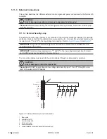
Page 64: ... 25 on page 56 and Figure 27 IMPORTANT A high limit humidistat is highly recommended to prevent over humidification and potential damage to property IMPORTANT Install a jumper between pins 1 and 2 in the low voltage terminal strip if no exter nal On Off devices are connected to the security loop The connecting cables must lead into the control cabinet through a cable gland or grommet CAUTION Risk ...

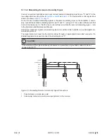
Page 65: ... to utilize the second modulating signal refer to the Operation and Maintenance Manual Alternately transducer signals or demand signals can be written to the humidifier via a valid digital com munication protocol The signal cable must lead into the control cabinet through an appropriate strain relief connector If a shielded signal cable is used connect the shielding to pin 3 CAUTION If the shieldi...

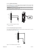
Page 66: ...6 will output 24 VDC Note By default the jumper JP2 is set to 10 VDC so that the output can also be used for test purposes Figure 29 INTERNAL EXTERNAL 1 2 3 4 5 6 7 8 9 24 VAC Security Loop GND GND FTBD CH 1 CH 2 24 VDC 1 10V 24V JP2 1 2 3 24 V On Off Humidistat Connection 1 Humidistat 24 VDC On Off 5 11 3 4 Full Tank Blowdown Signal Connection If an external full tank blowdown signal is used conn...

Page 67: ...O when a warning appears on the touchscreen panel of the humidifier and the status LED turns yellow in color Note This relay can be configured in the control software to indicate status updates or system warn ings refer to the Remote Fault Board tab in the Operation and Maintenance Manual Steam this normally open NO relay closes when the unit is producing steam Unit on this normally open NO relay ...

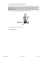
Page 68: ...l Figure 3 on page 10 for power requirement and sizing of fused disconnect switch IMPORTANT Make sure that the main power cable is proper grounded through the ground lug inside the control cabinet All wiring must be in accordance with national and local electrical codes Figure 32 N L EXTERNAL INTERNAL 1 2 Single Phase Power Supply Connections 1 Switch disconnect external fused 2 Terminal block pow...

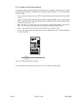
Page 69: ...r last unit in the network Figure 33 ethernet USB comm port RFB ACC J22 LED J18 display J17 display U U U U J15 J1 J2 J3 J6 J12 J10 J14 J19 J23 J21 J16 CONTROL BOARD Modbus Linkup battery SIM card JP11 JP8 JP7 JP4 J6 Modbus JP8 JP7 JP4 Modbus Connection on Nortec GS Humidifier JP4 Jumper for activating the termination resistor for Modbus or BACnet MSTP network J6 Connector Modbus RS485 interface J...

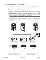
Page 70: ...t a multi strand twisted pair shielded cable 18 24 AWG 120 Ω between the J10 connectors on the control board of each Nortec GS humidifier in the Linkup system IMPORTANT Do not reverse polarity 4 Install the termination jumper JP8 in the control board of the last extension unit in the Linkup system 5 Finally refer to the Operation and Maintenance Manual to set up the multi unit configuration in the...

Page 71: ...igure 3 on page 10 Power supply have an external dedicated fused disconnect switch All wiring done according to the wiring diagram and instructions in this manual Main power cable proper grounding through the ground lug inside the electric cabinet All cables fastened securely All cables free of tension and pass through cable glands or grommets Electrical installation meet the applicable national a...

Page 72: ...66 2583703_EN_1608 Nortec GS This page intentionally left blank ...
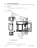
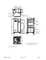
Page 73: ...S 50 3 in 75 mm GS 100 ø ø Power In 7 8 in 22 mm ø Water Inlet 3 4 in BSPP thread Condensate Outlet CS NX only 3 8 in 9 5 mm ø Drain Outlet 7 8 in 22 mm ø 8 203 3 5 90 2 9 74 19 485 16 7 423 16 5 419 4 0 102 5 9 150 6 9 176 3 4 87 3 0 76 6 3 161 3 6 92 8 5 215 3 9 99 21 2 539 15 7 398 23 5 598 43 4 1102 11 5 292 Controls In 7 8 in 22 mm ø Metric to imperial size adaptor supplied with unit BSPP to ...

Page 74: ... mm ø Gas Inlet 3 4 in NPT Power In 3 4 in 19 mm ø Condensate Outlet CS NX only 1 2 in 13 mm ø Drain Outlet 7 8 in 23 mm ø 27 0 684 3 2 80 18 7 474 11 6 295 12 7 322 8 6 219 Water Inlet 3 4 in BSPP 23 7 603 1 5 37 Exhaust Outlet 80 mm GS 150 CS NX ø Metric to imperial size adaptor supplied with unit BSPP to NPT adaptor supplied with unit Air Inlet 3 in 75 mm ø Nortec GS 150 ...

Page 75: ...In 3 4 in 19 mm ø Condensate Outlet CS NX only 1 2 in 13 mm ø Drain Outlet 7 8 in 23 mm ø 37 8 960 3 1 79 24 1 612 8 9 226 11 7 297 8 6 218 Water Inlet 3 4 in BSPP 55 5 1410 51 5 1309 39 7 1009 7 8 199 6 1 155 25 1 638 4 3 108 27 7 705 1 6 42 1 0 25 3 5 89 33 0 839 0 8 20 Metric to imperial size adaptor supplied with unit BSPP to NPT adaptor supplied with unit Nortec GS 200 300 ...

Page 76: ...ensate Outlet CS NX only 1 2 in 13 mm ø Drain Outlet 7 8 in 23 mm ø 62 2 1580 3 1 79 32 7 830 4 6 118 13 2 336 32 3 821 Water Inlet 3 4 in BSPP 55 5 1410 51 5 1309 39 7 1009 6 1 154 7 8 199 25 1 638 4 3 108 27 7 705 1 6 42 1 0 25 3 5 89 50 8 1290 Metric to imperial size adaptor supplied with unit BSPP to NPT adaptor supplied with unit 1 1 4 in to 1 in NPT adaptor supplied with unit Nortec GS 450 ...

Page 77: ...ensate Outlet CS NX only 1 2 in 13 mm ø Drain Outlet 7 8 in 23 mm ø 73 2 1859 7 1 180 32 7 830 4 6 116 13 2 335 32 3 821 Water Inlet 3 4 in BSPP 55 5 1410 51 5 1309 39 7 1009 6 0 151 7 8 199 25 1 638 4 3 108 27 7 705 1 7 42 1 0 25 3 5 89 58 9 1497 Metric to imperial size adaptor supplied with unit BSPP to NPT adaptor supplied with unit 1 1 4 in to 1 in NPT adaptor supplied with unit Nortec GS 600 ...

Page 78: ...72 Product Specifications 2583703_EN_1608 Nortec GS This page intentionally left blank ...

Page 79: ...for at least 12 in 300 mm before bend Steam line has minimum upslope of 10 or minimum downslope of 2 Steam line does not reduce in diameter except at the steam distributor and condensate line installed just before the restriction Steam lines do not merge except at the steam distributor through a Nortec adaptor Steam line does not sag Steam connections secured with clamps Clamps torqued adequately ...

Page 80: ...med with water Combustion Air Connection Space Air Installation Fresh combustion air requirements for the room space Table 14 on page 40 and all national and local regulations satisfied Elbow installed at the intake air inlet on Nortec GS 150 600 units Combustion Air Connection Sealed Combustion Installation All relevant national and local regulations for sealed combustion installation satisfied I...

Page 81: ...s fixed De pressurize gas supply line after leak test Electrical Connections Power supply meet the rated current draw limits shown on the specification label Figure 3 on page 10 Power supply have an external dedicated fused disconnect switch All wiring done according to the wiring diagram and instructions in this manual Main power cable proper grounding through the ground lug inside the electric c...

Page 82: ...iv Appendix A 2583703_EN_1608 Nortec GS This page intentionally left blank ...

Page 83: ... The warranties set forth herein are in lieu of all other warranties expressed or implied by law No liability whatsoever shall be attached to THE COMPANY until said products have been paid for in full and then said liability shall be limited to the original purchase price for the product Any further warranty must be in writing signed by an officer of THE COMPANY THE COMPANY s limited warranty on a...

Page 84: ... A 835 Commerce Park Ave Ogdensburg NY 1366 2209 CANADA 2740 Fenton Road Ottawa ON K1T 3T7 Tel 1 866 NORTEC1 Fax 613 822 7964 Email nortec humidity com Website www humidity com Consulting Sales and Service ...

Reviews: