56
Installation
2583703_EN_1608
Nortec GS
5.11.2
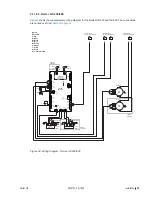
Wiring Diagrams
5.11.2.1
Nortec GS 50/100/150/200/300
Figure 25:
R
6 A
Drain
Pump
Fill 1
Stack
Hi-Limit
R
Bk
Float Board
J1
Bk
W
R
R
Y
Blower
Relay
7
8
3
4
5
1
6
2
N
L
EXTERNAL
INTERNAL
Transformer
24V
On/Off
Switch
1
2
3
4
Gr/Y
S
Legend:
Wire Colors
Bk - Black
Bl - Blue
Br - Brown
O - Orange
Y - Yellow
Gr - Green
Gr/Y - Green & Yellow
R - Red
W - White
L1
L2
Blower 1
M
PWM
PS -
PS +
GND
HS out
1
R
W
Bk
Gr
L1
L2
Blower 2
M
PWM
PS -
PS +
GND
HS out
1
R
W
Bk
Gr
Bk
W
W
R
Bk
Br
Gr
W
R
Bk
Gr
Bk
Gr
W
R
Pressure
Switch
Gas Valve1
Gnd
TH
V2
V1
Ignition
Module 1
Gnd
TH
V2
V1
Ignition
Module 2
Bk
R
Spark
Igniter
Spark
Igniter
Bk
R
R
W
R
Bk
Br
Gr
S
S
Y
R
Gr/Y
24
V
A
C
Security Loop
GND
GND
FTBD
CH
1
CH
2
+10 VDC
1 2 3 4 5 6 7 8 9
R
R
R
Y
Y
Gr
Fill 2
Tank
Hi-Limit
Y
Y
R
Tank
Temp
R
Bk
R
Bk
Bk
R
Bk
Gr/Y
Bk
R
Gr/Y
Bk
Gr/Y
Bk
R
CONTROL SIGNAL
CONNECTIONS
PRIMARY VOLTAGE
CONNECTION
EXTERNAL
INTERNAL
Bk Br
R Bk Br
M
R
Bk
R
M
Drain Valve
(optional)
Bk
Gas Valve2
2-Burner
Units Only
M
M
Micro
Pump1
Micro
Pump2
R
Y
Gr/Y
R
Bk
Bk
R
Gr
W
2-Burner
Units Only
2-Burner
Units Only
J2
J5
J15
J16
J14
J1
J10
J3
J7
J8
J17
J11
J9
J12
J6
J13
float
pwm1
pwm2
fill 1,2,3
ext
ntc
power
a/p
ignition1
ignition2
RS485-2
RS485-1
24Vout
pmp_fre
drn_blower
digi inputs
DRIVER
BOARD #1
R
J1
J2
PUMP MODULE
CS/NX Models
(
on Driver Board)
J18
CO
M
Remote Fault PCB
NO
NC
Steam
Unit ON
Error
Service
CO
M
NO
NC
CO
M
NO
CO
M
NO
ethernet
USB
comm port
RFB
ACC
J22
LED
J18
display
J17
display
U
U
U
U
J15
J1
J2
J3
J6
J12
J10
J14
J19
J23
J21
J16
INTEGRATED
CONTROL
BOARD
Modbus
Linkup
battery
SIM
card
JP11
JP8
JP7
JP4
Low voltage
terminal strip
Bk
R
3 or 4-Burner
Units Only
Continued on
next wiring diagram
D
C
3 or 4-Burner
Units Only
Continued on
next wiring diagram
3 or 4-Burner
Units Only
Continued on
next wiring diagram
A
3 or 4-Burner
Units Only
Continued on
next wiring diagram
B
Gr/Y
Gr/Y
Gr/Y
Gr/Y
Gr/Y
Gr/Y
Gr/Y
JP1
JP2
Wiring Diagram - Nortec GS 50/100/150/200/300
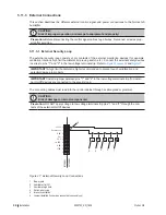
JP4 Jumper – for activating the termination resistor for Modbus or BACnet MSTP network.
J6 Connector, Modbus (RS485 interface)
JP7 Jumper – for activating Modbus or BACnet MSTP communication via connector J6.
JP8 Termination, Linkup system
J10 Connector, Linkup
Summary of Contents for GS
Page 3: ...INSTALLATION MANUAL Gas fired Steam Humidifier Nortec GS 2583703_EN_1608 ...
Page 12: ...6 For Your Safety 2583703_EN_1608 Nortec GS This page intentionally left blank ...
Page 14: ...8 Receiving and Storage 2583703_EN_1608 Nortec GS This page intentionally left blank ...
Page 20: ...14 Product Overview 2583703_EN_1608 Nortec GS This page intentionally left blank ...
Page 72: ...66 2583703_EN_1608 Nortec GS This page intentionally left blank ...
Page 78: ...72 Product Specifications 2583703_EN_1608 Nortec GS This page intentionally left blank ...
Page 82: ...iv Appendix A 2583703_EN_1608 Nortec GS This page intentionally left blank ...


