57
Installation
Nortec GS
2583703_EN_1608
5.11.2.2
Nortec GS 450/600
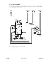
Figure 26
shows the supplementary wiring diagram for the Nortec GS 450 and GS 600. The connections
are carried over from
Figure 25 on page 56
.
Figure 26:
L1
L2
Blower 4
M
PWM
PS -
PS +
GND
HS out
1
R
W
Gr
Bk
L1
L2
Blower 3
M
PWM
PS -
PS +
GND
HS out
1
R
W
Gr
Bk
J2
J5
J15
J16
J14
J1
J10
J3
J7
J8
J17
J11
J9
J12
J6
J13
float
pwm1
pwm2
fill 1,2,3
ext
ntc
power
a/p
ignition1
ignition2
RS485-2
RS485-1
24Vout
pmp_fre
drn_blower
digi inputs
DRIVER
BOARD #2
R
J1
J2
PUMP MODULE
CS/NX Models
( on Driver Board)
J18
Gas Valve3
Gnd
TH
V2
V1
Ignition
Module 3
Gnd
TH
V2
V1
Ignition
Module 4
Bk
R
Spark
Igniter
Spark
Igniter
Bk
R
R
Gr/Y
Bk Br
R
Gr/Y
Bk Br
Gas Valve4
Bk
4-Burner
Units Only
M
M
Micro
Pump3
Micro
Pump4
Bk
R
Gr
W
Fill 3
R
Bk
W
R
Bk
Gr
Bk
Gr
W
R
S
S
Fill 4
R
Bk
Gr/Y
Gr/Y
Bk
R
R
4-Burner
Units Only
4-Burner
Units Only
C
D
Continued from
previous wiring diagram
Continued from
previous wiring diagram
Y
A
B
Continued from
previous wiring diagram
Legend:
Wire Colors
Bk - Black
Bl - Blue
Br - Brown
O - Orange
Y - Yellow
Gr - Green
Gr/Y - Green & Yellow
R - Red
W - White
Gr/Y
Gr/Y
JP1
JP2
Wiring Diagram - Nortec GS 450/600
Summary of Contents for GS
Page 3: ...INSTALLATION MANUAL Gas fired Steam Humidifier Nortec GS 2583703_EN_1608 ...
Page 12: ...6 For Your Safety 2583703_EN_1608 Nortec GS This page intentionally left blank ...
Page 14: ...8 Receiving and Storage 2583703_EN_1608 Nortec GS This page intentionally left blank ...
Page 20: ...14 Product Overview 2583703_EN_1608 Nortec GS This page intentionally left blank ...
Page 72: ...66 2583703_EN_1608 Nortec GS This page intentionally left blank ...
Page 78: ...72 Product Specifications 2583703_EN_1608 Nortec GS This page intentionally left blank ...
Page 82: ...iv Appendix A 2583703_EN_1608 Nortec GS This page intentionally left blank ...


