Nordson iDry Series Product Manual Download Page 52

Nordson iDry

r

 Series Induction Dryers

46

Part 1075452

04

E

 2016 Nordson Corporation

Coil and Coil Tube Replacement 

 (contd)

1

7

2

4

3

5

6

8

8

9

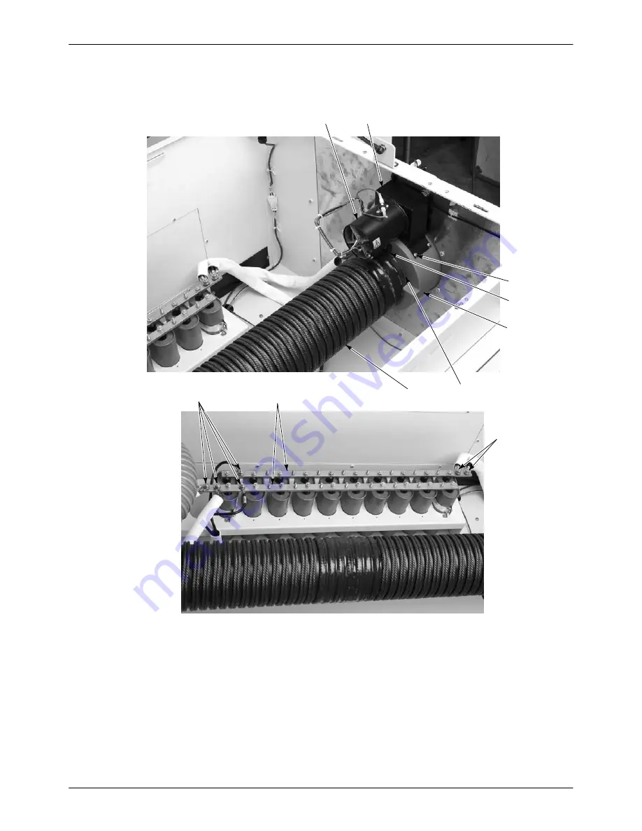
Figure 43 Coil and Tube Replacement (Air Heater at Entrance End Shown)

1. Vent housings
2. Air Heater
3.  Screws (4 on each hub)

4. Hubs
5.  Nylon slotted screws
6.  Glass tube (inside coil)

7. Coil
8.  Coil connections (typical)
9. Bus bars

Summary of Contents for iDry Series

Page 1: ...RDSON CORPORATION AMHERST OHIO USA For parts and technical support call the Industrial Coating Systems Customer Support Center at 800 433 9319 or contact your local Nordson representative This documen...

Page 2: ...son Corporation publication which is protected by copyright Original copyright date 2007 No part of this document may be photocopied reproduced or translated to another language without the prior writ...

Page 3: ...Change Record i Part 1075452 04 E 2016 Nordson Corporation Change Record Revision Date Change 04 03 16 Ambient Temperature Compensation instructions added...

Page 4: ...Change Record ii Part 1075452 04 E 2016 Nordson Corporation...

Page 5: ...and Line Connections 10 Coil and Tube Installation 11 System Wiring 12 Schematics and Wiring Diagrams 12 Power Input 12 External Interlock 14 Connecting the External Interlock 14 Disabling Customer I...

Page 6: ...e Power Setpoint 32 High and Low Alarms 32 Faults 32 Navigation Screen 33 Ambient Temperature Compensation 34 Ambient Temperature Compensation Setup 34 How to Change the Setpoint Temperature from the...

Page 7: ...nd high voltage electrical equipment S can safely perform their assigned tasks S are familiar with all relevant safety rules and regulations and are physically capable of performing their assigned tas...

Page 8: ...tem is operating properly to prevent dangerous concentrations of volatile particles or vapors S Keep clear of moving equipment Before adjusting or servicing moving equipment shut off the power supply...

Page 9: ...materials Shut off power at a disconnect switch first to prevent sparking Allow 10 minutes for all internal energy storage devices to completely discharge S Know where emergency stop buttons shutoff...

Page 10: ...the line starts heating within the can ends instantly starts Since heat is created directly within the ends there is no thermal inertia When the line stops heating instantly stops This produces a ver...

Page 11: ...he motion sensor detects can ends moving through the dryer 3 Operator Control Console Contains the operator interface terminal touch screen which contains all operator control functions including warn...

Page 12: ...power supplied to the coil to eliminate temperature variations due to line voltage fluctuations applied compound weight and can end start temperature A blower in the controller power inverter enclosu...

Page 13: ...6 Nordson Corporation Coil Tray Coil and Tube Assembly Motion Sensor Thermocouple Feed Direction 0N CH AL Entrance Exit Controller and Power Inverter Enclosure Figure 3 Theory of Operation Coil Windin...

Page 14: ...vation Altitude Less than 1524 meters 5000 ft Above 5000 ft system must be de rated Contact your Nordson representative Power Supply Requirements 360 415 Vac 50 Hz or 440 480 Vac 60 Hz 3 phase Class J...

Page 15: ...bvious shipping damage and shortages If you see any damage or shortages notify the shipper and your Nordson representative immediately NOTE A 5 16 inch hex wrench is required to unlock and lock the co...

Page 16: ...1 meter 39 in of space at the rear of the dryer to remove the access panel for power and interlock connections and repairs S Provide 1 meter 39 in of space in front of the dryer to open the enclosure...

Page 17: ...d of the coil tray lid Lift the lid to the full up position 3 Remove the screws 1 securing the air heater and exhaust vent to the entrance and exit hubs Move the air heater and exhaust vent away from...

Page 18: ...end to the common bus bar and all terminations at other end to other common bus bar 1 2 3 4 5 Figure 8 Coil and Tube Installation 1 Air heater and exhaust vent screws 4 on each hub 2 Cushion and hold...

Page 19: ...r death from electrical shock See Figure 9 Line power is supplied to the system through a 3 4 in 1 9 cm conduit fitting in the lower left hand corner of the dryer exit end NOTE Wire gauge must be copp...

Page 20: ...Vdc source at 100 mA to power an internal relay coil refer to Note below The external 24 VDC power source is not referenced to the dryer ground The interlock indicates to the dryer system that the pr...

Page 21: ...contact is off when S The dryer is turned off S Any fault on the operator panel is activated Status Contact Connection Terminal 32 Output Contact output Motion Sensor See Figure 11 The motion sensor...

Page 22: ...flow from the exhaust vents Return Shipping Instructions Refer to page 9 for lift points Domestic USA 1 Remove the glass coil tube and coil Carefully pack the tube and coil separately 2 Remove the le...

Page 23: ...locked from the Options screen which is a password protected screen If you do not have access to the screens required for setup contact your Nordson representative Setup normally needs to be performed...

Page 24: ...oved from production Keyence Motion Sensor Sensitivity Adjustment WARNING Laser radiation Do not look directly into the laser beam or its reflection from can bodies Doing so could result in serious ey...

Page 25: ...r beam or its reflection from can bodies Doing so could result in serious eye injury The SICK laser sensor focal point is adjustable between 30 60 mm from the sensor face Adjust the distance screw for...

Page 26: ...language Other languages available are Spanish French and German 1 Press the green power button on the operator terminal to turn on the dryer 2 The Nordson iDry splash screen appears then the Auto sc...

Page 27: ...during the ramp time ramp time is the time it takes for a can end to travel the length of the dryer The ramp mode is activated every time coil power is turned on 1 Press the green power button on the...

Page 28: ...ssword protected by default To access this screen you must first enable it from the Options Setup screen Refer to page 28 Figure 19 Manual Mode Screen 9 Run can ends through the dryer at the desired p...

Page 29: ...ing delays turning off coil power when can end motion stops This prevents control cycling to ramp mode each time the line momentarily stops The factory default setting is 3 seconds Do not set the moti...

Page 30: ...EXTERNAL INTERLOCK TIMER field and set the desired time with the keypad 3 Touch ENT to save your setting External Interlock Activation The External Interlock must be wired and activated before you can...

Page 31: ...various metal types Touch the TEMPERATURE OFFSET field and use the keypad to set the desired offset Touch ENT to save your setting Power Limits Power Limit Control Touch the POWER LIMIT button to tog...

Page 32: ...tional band P heat S Integral I heat S Derivative D heat These parameters make up the PID loop that controls the duty cycle used to regulate the amount of power applied to the induction coil PID setti...

Page 33: ...Alarm Setpoints If the product temperature increases to the ALARM HIGH SETPOINT or decreases to the ALARM LOW SETPOINT an alarm fault is issued and the dryer will shut down The factory default settin...

Page 34: ...tton to toggle change access ON or OFF for the following screens and functions The factory default setting for each is listed along with the page number for the instructions for setting each screen s...

Page 35: ...n disconnect on left side of control enclosure S Emergency Stop switch S Power pushbutton indicator Start S Off pushbutton Stop S Operator Interface Terminal OIT Operator Interface Terminal Emergency...

Page 36: ...oubleshooting on page 41 to correct the problem 4 Start your production line and run can ends through the dryer The system powers the induction coil and heats the can ends whenever the motion sensor d...

Page 37: ...etpoint temperature value 5 A numerical keypad will appear Set a new setpoint and touch the ENT button on the keypad to save the setting Manual Mode The dryer can also be operated in Manual mode The M...

Page 38: ...nd the actual temperature rises above the Alarm High deviation or falls below the Alarm Low deviation the dryer will continue to operate for a preset period of time Temperature Alarm Delay If the actu...

Page 39: ...ovides access to the system settings auto and manual screens and operator language screen Touching the MENU button on any screen will open this screen NOTE Some screens are password protected If they...

Page 40: ...p page for ambient compensation Ambient Temperature Compensation Setup 1 From the main Menu Navigation screen select the CONFIG button Password required 2 See Figure 31 Select the AMBIENT TEMP COMPENS...

Page 41: ...dard iDry Temperature Setup screen will be locked from use Use the Ambient Compensation Setup screen to change setpoint temperature 6 See Figures 33 and 34 Verify that the following screens are automa...

Page 42: ...MP button from the Auto Run screen See Figure 36 2 Select the ENTER NEW DATA from the Warning screen 3 A Pop up screen will appear Enter password 4 Enter information into the PRODUCT TEMP SETPOINT fie...

Page 43: ...NOTE A password is required to perform the following procedure 1 To cancel temperature compensation mode select the MENU button to transfer to the Menu Navigation screen Then select the CONFIG ATC but...

Page 44: ...data can be monitored to compare original presets to current settings 1 Select the MENU button 2 See Figure 38 From Menu screen select the PLC IO button 3 From PLC IO screen select the AMB C DATA But...

Page 45: ...down the dryer press the OFF pushbutton on the operator panel NOTE While you can stop the dryer by pressing the EMERGENCY STOP button or by switching the main disconnect switch to the OFF position you...

Page 46: ...for wear and good contact with the can ends Replace the thermocouple as needed Motion Sensor Clean the sensor head lens with a clean soft cloth When the system is not being used cover the lens with t...

Page 47: ...ipment failure NOTE Use the schematics provided with your system when performing troubleshooting procedures Problem Possible Cause Corrective Action 1 Dryer will not turn on when POWER button is press...

Page 48: ...ll access panel properly 8 Temperature overshoots on startup Incorrect ramp mode power level adjustment Adjust setting page 21 9 System stays in Ramp Mode Never switches to Run Mode ON Motion timer se...

Page 49: ...k circuit failure or incorrect product load DISCONNECT AND LOCKOUT POWER BEFORE PROCEEDING Perform diagnostic test on power processing subsystems RF board driver failure 19 EXT INTLK TIMED OUT fault C...

Page 50: ...Mode To switch to manual mode from the Auto mode screen 1 Touch the MENU button The Navigation screen opens 2 Touch the MAN Manual Control button If enabled the Manual mode screen opens 3 Enter the d...

Page 51: ...ety switches Disarming diagnostic devices will void the warranty and may cause equipment failure Coil and Coil Tube Replacement The coil and coil tube can be replaced separately They both must be remo...

Page 52: ...on Coil and Coil Tube Replacement contd 1 7 2 4 3 5 6 8 8 9 Figure 43 Coil and Tube Replacement Air Heater at Entrance End Shown 1 Vent housings 2 Air Heater 3 Screws 4 on each hub 4 Hubs 5 Nylon slot...

Page 53: ...ub mounting screws and check the tube clearance c Trim away any protruding shim stock 12 Re install the two cushions and screws into the entrance and exit hubs 13 Re install the heater blower and exha...

Page 54: ...iDryr Series Induction Dryers 48 Part 1075452 04 E 2016 Nordson Corporation Air Filter Replacement See Figure 45 To replace the filter pull it out of the right side of the holder Figure 45 Filter Repl...

Page 55: ...f plant Serial number and model number of unit Phone and fax number Name of person requesting service Nature of the service call Parts Ordering Information All parts can be ordered through Nordson Cor...

Page 56: ...8 52 125 60 53 127 40 54 129 20 55 131 00 56 132 80 57 134 60 58 136 40 59 138 20 60 140 00 61 141 80 62 143 60 63 145 40 64 147 20 65 149 00 66 150 80 67 152 60 68 154 40 69 156 20 70 158 00 71 159...

Page 57: ...This product has been manufactured according to good engineering practice The product specified conforms to the directive and standards described above Certificates TUV EN60204 ISO EN12100 Cert for EU...

Reviews: