background image

TRITURATOR

MULCHER

Trince spostabili polivalenti e robuste per la frantumazione di legna sottile,
erba e per la manutenzione di bordi stradali, prati, parchi e giardini.
Disponibili nelle versioni “destra” o “sinistra” (

) e con anti-shock a richiesta.

Des broyeurs deportables polyvalentes et robustes parfaitement adaptés pour petites
branches, sarments, herbe et pour l'entretien de gazons, bord de routes, parcs, jardins,
terrains de sport.
Disponibles en version droit ou gauche (

) et avec dispositif antichoc sur demande.

Sturdy multi-purpose shifting mulchers for shredding grass, light wood and even ideal for
upkeeping road sides, sports fields, parks and gardens.
Right or left (

) hand versions available. Anti-shock device upon request.

Starke und vielseitige Mulchgeräte mit Parallelogrammverschiebung eignen sich besonders
zum Zerkleinern von Schnittholz und Gras wie zur Bearbeitung von Grünflächen in Park- und
Sportanlagen sowie Straßenstreifen.
Rechtsausführung oder Linksausführung (

) lieferbar. Schwingungsdämpfer auf Wunsch.

Trituradoras desplazadas polivalentes y robustas para desmenuzar madera fina, sarmientos de
vid, hierba y para el cuidado de prados, lados de carreteras, parques y jardines.
Disponibles en version derecha o bien izquierda (

). Bajo demanda aparato anti-shock.

TB

Summary of Contents for TB 151

Page 1: ...OPERATOR S MANUAL SHREDDERS TB 151 181 211 Cod mum TB_G English 04 2006...

Page 2: ......

Page 3: ...DO NOT ASSUME YOU KNOW HOW TO OPERATE AND MAINTAIN YOUR MACHINE before reading this manual carefully KEEP THIS MANUAL AVAILABLE FOR REFERENCE Pass it on to the next owner if you re sell the machine Y...

Page 4: ...iption of symbols used in this document 6 Safety instructions 7 Location and description of safety decals on the machine 15 Machine specifications 21 Description and glossary 21 Technical specificatio...

Page 5: ...rking position 33 Machine use 34 Optional equipment 36 Cable controls 36 Double skinned plate 36 Movable bottom land roller 37 Rounded skids 38 Antishock unit arm 39 Constant velocity double joint 39...

Page 6: ...4 Identification of the machine TB 151 181 211 Shredders IDENTIFICATION OF THE MACHINE 1 Front view 2 Rear view...

Page 7: ...sponding to the equipment fitted on your machine Kit no 001732 Cable controls Kit no 400794 Double skinned plate TB 151 Kit no 400793 Double skinned plate TB 181 Kit no 400796 Double skinned plate TB...

Page 8: ...tes a potentially hazardous situation that if not avoided could result in serious bodily injury This symbol is used to identify special instructions or procedures which if not followed strictly could...

Page 9: ...ly be operated maintained and repaired by competent persons who are familiar with machine specifications and operation and aware of safety regulations for preventing accidents The operator must impera...

Page 10: ...re firmly in place and in good condition Immediately replace any worn or damaged guard Precautions when driving Precision steering tractor adherence road holding and efficient braking are influenced b...

Page 11: ...io is fulfilled M x S1 S2 0 2 x T x i Z x d i i Tractor wheel wheelbase d Distance of the front axle from ballast S1 Distance of the ball joints of lift lower links from tractor rear axle S2 Distance...

Page 12: ...a hose depressurize the hydraulic circuit To avoid making wrong connections mark hydraulic couplers and corresponding hoses with colours WARNING Functions could be reversed for example lift lower and...

Page 13: ...l provided with the PTO shaft Precautions during manoeuvres When moving the machine from the transport position to the working position and vice versa make sure that nobody is within the machine pivot...

Page 14: ...ake sure that the parts of the machine that need to be lifted for maintenance or repair work are firmly propped up Before any work is done on the electric circuit or before any electric welding is car...

Page 15: ...exterior Increase the cutting height to avoid contact with stones or rocks Never start the shredder when there are people nearby Even when the machine is used in accordance with its purpose objects m...

Page 16: ...source has stopped the rotors can continue turning for a time Stay away from the machine until all moving parts have come to a complete standstill If an obstacle is hit disengage the PTO drive stop t...

Page 17: ...s 3 Location and description of safety decals on the machine Location of safety decals 10 4 10 10 6 16 9 11 5 1 4 0018642 0018661 0018661 0018661 3 0018645 0018658 133047 0018647 8 134384 2 0018650 12...

Page 18: ...ore leaving the tractor or before adjusting maintaining or repairing the machine disengage the PTO drive turn off the engine remove ignition key and wait until all moving parts have come to a complete...

Page 19: ...ine is running the PTO drive engaged and the moving parts have not come to a complete stop Moving elements 5 Do not open or remove guards when the engine is on Support wheels 6 At work the support whe...

Page 20: ...there is a crushing risk before all moving parts have come to a complete stop Danger of falling 8 Do not ride on the machine Power requirement 9 Machine preset for a 540 drive Anchoring point 10 Indi...

Page 21: ...e Use of guards 12 Wear the appropriate protective clothing for the work in hand gloves shoes goggles helmet ear protectors etc Risk of injuries 13 Before adjusting maintaining or repairing the machin...

Page 22: ...t stay between the machine and the tractor Risk of entanglement 15 Stay clear of rotating drive line Projections 16 Stones and other debris projected by the moving parts can travel a long distance Alw...

Page 23: ...ECIFICATIONS 1 Description and glossary 0 1 Three point hitch coupler 2 Shredding unit 3 Offset cylinder 4 Shredding unit pivoting cylinder 5 Lock pin 6 Antishock unit 7 Side guard 8 Offset arm 9 Roll...

Page 24: ...tion frequency rpm 540 540 540 Quantity type of belts n 3 SPBX 1270 n 3 SPBX 1270 n 3 SPBX 1270 Rotor speed rpm 2218 2218 2218 Knives peripherical speed m s 48 49 49 Cutting diameter mm 413 420 420 Nu...

Page 25: ...ements A PTO shaft 1 3 8 6 splines A 3 point hitch 2 hydraulic hoses that control the lateral offset cylinder 2 hydraulic hoses that control the shredding unit cylinder Preparing the tractor The machi...

Page 26: ...he machine from the ground Fold parking stand upwards and lock it 1 Adjust stabilizers of lower links to prevent side to side movements of the machine HYDRAULIC Connections Offset cylinder Connect hyd...

Page 27: ...As a safety measure a clearance L of at least 25 mm 1 must be maintained When the PTO shaft is in its maximum extended position the tube overlap must be more than 250 mm 10 If this is not the case Ma...

Page 28: ...owards to increase the hydraulic flow The machine reacts more rapidly during manoeuvres Towards to reduce the hydraulic flow The machine reacts more slowly and smoothly during manoeuvres Tighten count...

Page 29: ...unit s positioning Vertical positioning Place side guard in high position Tilted positioning Place side guard in low position Side guard adjustment Remove the mounting bolts 1 Place guard in holes co...

Page 30: ...aN m 59 lbf ft Uncoupling the machine Place the machine in horizontal and central working position behind the tractor Lock hitch frame using lock pin Lower and lock parking stands 1 Lower the tractor...

Page 31: ...nt use appropriate lift straps chains or any other equipment in perfect working order complying with safety standards in force for this type of equipment and with capacities that exceed the total weig...

Page 32: ...shredding unit in horizontal position Fully raise tractor lift linkage The machine is in transport position Before placing the machine into transport position Wait until the rotating parts have come...

Page 33: ...transport 31 TB 151 181 211 Shredders 2 Conformity with the road regulations Check that reflectors are clean Before driving the machine on public roads ensure that the machine meets current highway c...

Page 34: ...uring work Unlock and place lock pin 1 in its holder 2 Description of the working positions The machine can be used in 4 positions Check that nobody is within the machine operating area The machine ca...

Page 35: ...r lift linkage until the rear roller touches the ground Adjust lift linkage height to obtain a perfectly horizontal position The cutting tools must never touch the ground Relationship between the work...

Page 36: ...ejection of stones or foreign objects over a wide radius If using a tractor with a cab that is not sound proofed or pressurized the operator must use individual protection equipment Ear protections i...

Page 37: ...lift linkage Offset machine Lower the tractor three point linkage to rest the machine on the ground Groundspeed Groundspeed must be adapted to the encountered working conditions Side offset manoeuvres...

Page 38: ...etented position to obtain a constant flow Operate cable controls to monitor the required function 2 Double skinned plate Kit no 400794 TB 151 Kit no 400793 TB 181 Kit no 400796 TB 211 Make sure that...

Page 39: ...out hose 1 or bottoms 2 To replace the roller Lift the machine slightly off the ground Unscrew 2 bolts 3 Remove bolts 4 Fit the movable bottom land roller Place roller in holes 6 corresponding to the...

Page 40: ...dders 4 Rounded skids Kit no 401269 The rounded skids improve crosswise machine gliding with regards to the direction of travel Fitting Remove nuts 1 Remove skid 2 Fit rounded skid 3 Insert and tighte...

Page 41: ...cally its initial position after having cleared the obstacle The safety breakback is adjusted by means of nuts 1 The measure X is factory set at 80 mm 3 3 This adjustment suits most conditions of use...

Page 42: ...he machine turn off ignition key and wait until all moving parts have come to a complete stop 0018650 Every 4 hours Every 8 hours Every 20 hours Every 50 hours Every 250 hours or at the end of the sea...

Page 43: ...the rotor and the machine inner panels 3 Lubrication The pictorials show the points to be greased Part no 0012215 Part no 0011999 Clean grease zerks before greasing Every 4 hours Grease Grease rotor...

Page 44: ...rs transmission tube 2 Every 50 hours guide rings 3 Every 8 hours Check gearbox oil level Place the machine horizontally Remove level plug 1 The oil level must reach lower part of level plug hole top...

Page 45: ...ide Remove the side guard 1 Remove side guard 2 Loosen adjustment screws 3 to slacken belts Remove the 3 V belts 7 Remove pulley 8 Remove the mounting bolts 4 Remove adjustment screws 3 Remove central...

Page 46: ...hrough the opening of the filler plug Reinstall filler plug 6 Reinstall central gearbox Reinstall attachment bolts 4 Tightening torque 10 daN m 74 lbf ft Reinstall adjustment screws 3 Reinstall pulley...

Page 47: ...ntenance and storage 45 TB 151 181 211 Shredders Check cutting tools and their fixing elements Cutting tools Universal knives Type 01 1 Hammer knives Type 06 K 2 Pivoting universal knives Type 08 3 1...

Page 48: ...tion of the mounting hole L2 must not exceed 18 mm 0 71 Hammer knives The cutting tool length L1 must exceed 90 mm 3 54 Ovalisation of the mounting hole L2 must not exceed 18 mm 0 71 Fixing elements C...

Page 49: ...trically opposite Fit the knives according to the direction of travel of the machine Check that there is still 1 to 2 mm 0 04 0 08 mm play between the pair of knives and the supports Checking the bala...

Page 50: ...211 Shredders Belt tension Checking the tension Through the side guard slot Apply a force of 2 5 daN 5 5 lbf on the belt the belt should not deflect more than H 5 5 mm 0 2 Check belt tension After the...

Page 51: ...Turn the adjustment screws 5 and nuts 6 equally until reaching the optimum tension Tighten bolts 3 Tighten nuts 4 Check that pulleys are in line Reinstall side guards By adjusting 5 and 6 equally the...

Page 52: ...ransmission shaft Remove side guard 1 Remove side guard 2 Using a ruler check that pulleys are in line 3 The ruler must be in contact with both sides of the pulleys 3 If the ruler 3 does not touch use...

Page 53: ...ck their condition At the start of each season Read through the operator s manual again Check that the machine is greased Check all the knives and fixings and replace if necessary Check that all nuts...

Page 54: ...ack of oil B No oil Top up until proper oil level is reached Replace gearbox Fast knife or hammer knife wear A Working position too low interference with the ground Adjust working height Drive shaft o...

Page 55: ...Limited warranty 53 TB 151 181 211 Shredders LIMITED WARRANTY...

Page 56: ......

Page 57: ......

Page 58: ......

Page 59: ...Trince Broyeur Mulcher Mulchger t TB DX 02 03 2009...

Page 60: ...EXIBLE REMOTE CONTROLS Table J90R1218 B SIMPLE EFFECT FLEXIBLE REMOTE CONTROLS Table J90R1094 A ARMS BUMPERS Table 680 TRANS SHAFT Table 829 TRANS SHAFT Table 880 TRANS SHAFT Table J90R1215 A TRANS SH...

Page 61: ...5 Quantit richiesta To order the spare parts of our machines you must correctly specify the following 1 Type of machine 2 Serial number of the machine 3 Code number 4 Description 5 Quantity required P...

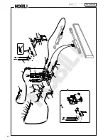
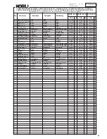
Page 62: ...Data ultima modifica 19 10 2006 1 4 52 54 55 56 53 42 41 39 43 40 51 50 5 6 63 59 32 22 21 57 59 58 7 56 55 57 55 55 59 8 9 10 12 13 34 54 37 14 33 55 56 15 16 18 38 36 35 17 30 26 60 27 28 29 28 19...

Page 63: ...z L 482 Rubber Caoutchouc Gummi 28282 3 33 Slitta protezione SX Slide Glissi re Schlitten 29265 1 29265 1 29265 1 34 Vite TSCE M10x30 Screw Vis Schraube 0410025 2 0410025 2 0410025 2 35 Dado aut M10 S...

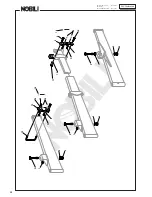
Page 64: ...6 TAV J90R1216 A Data di emissione 29 10 2007 Revisione Data ultima modifica 14 03 2008 14 14 10 6 7 8 5 9 2 15 13 13 13 12 12 11 1 11 14 12 11 5 4 15 3...

Page 65: ...heibe 0011815 3 0011815 3 0011815 3 06 Raccordo occhio 3 8 Coupling Raccord Anschlussst ck 002255 1 002255 1 002255 1 07 Rubinetto 3 8 Tap Robinet Hahn 002257 1 002257 1 002257 1 08 Nipplo 3 8 Nipple...

Page 66: ...2 27 64 65 28 31 30 67 32 42 5 6 6 35 38 36 36 36 39 37 37 37 36 36 36 36 46 49 48 47 61 63 36 36 37 36 37 34 53 25 40 40 37 41 41 67 45 13 12 5 8 9 9 59 60 9 6 9 10 6 7 5 60 16 6 26 43 83 84 85 43 50...

Page 67: ...000029 1 30 Boccola 44 x 40 x 40 Bush Douille B chse 000033 1 000033 1 000033 1 31 Ingrassatore M 6 Greaser Lubrifieur Fettb chse 0011836 1 0011836 1 0011836 1 32 Biella sx Connection rod Bielle Pleue...

Page 68: ...6 68 72 95 94 93 75 76 77 79 76 78 80 73 74 69 70 71 15 33 12 14 17 24 22 27 64 65 28 31 30 67 32 42 5 6 6 35 38 36 36 36 39 37 37 37 36 36 36 36 46 49 48 47 61 63 36 36 37 36 37 34 53 25 40 40 37 41...

Page 69: ...ola Bush Douille B chse 132605 2 132605 2 132605 2 78 Dado aut M 16 Selflocking nut Ecrou autobloquant Selbstsichernde Mutter 0911603 2 0911603 2 0911603 2 79 Braccio scorrevole Arm Bras Arm 132363 1...

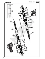
Page 70: ...TAV 827 7 13 6 14 13 33 34 32 31 14 13 3 4 5 3 14 18 19 35 21 22 23 8 2 9 10 11 12 15 16 17 10 8 2 7 23 25 1 30 28 29 27 26 24 20 Data di emissione 12 06 2002 Revisione Data ultima modifica 12 07 200...

Page 71: ...18 1 4808015 1 18 Spessore 2 mm Spacer Entretoise Distanzst ck 0012109 2 0012109 2 0012109 2 19 Flangia rotore sx Flange Flasque Flansch 129258 1 129258 1 129258 1 20 Prolunga ingrassatore Extension P...

Page 72: ...14 TAV 828 21 25 4 26 9 8 24 23 22 29 21 20 19 18 17 16 15 14 13 12 11 10 9 8 7 6 5 3 2 1 22 28 27 30 Data di emissione 12 06 2002 Revisione Data ultima modifica 02 03 2009...

Page 73: ...cinetto conico Bearing Roulement Lager 0010142 1 0010142 1 0010142 1 14 Spessore 0 3 Spacer Entretoise Distanzst ck 0012169 0012169 0012169 15 Spessore 0 4 Spacer Entretoise Distanzst ck 0012170 00121...

Page 74: ...16 TAV 1011 Data di emissione 16 12 2004 Revisione Data ultima modifica 02 03 2009 8 2 4 10 43 42 41 34 13 29 5 3 28 12 26 15 11 9 14 7 13 20 27 33 1 6 35 36 44 25 40 37 38 39 45 46...

Page 75: ...1 20 Spessore Ring Bague Ring 002082 1 25 Molla Spring Ressort Feder BP91007 3 26 Cuscinetto conico Ball bearing Roulement bille Kugellager BP91067 1 27 Cuscinetto a sfere diritto Ball bearing Rouleme...

Page 76: ...18 TAV 826 10 10 13 11 3 20 19 11 12 11 12 9 8 6 11 1 1 11 14 18 17 17 16 2 15 15 16 2 11 1 1 11 9 8 7 6 4 5 11 3 11 12 11 12 Data di emissione 12 06 2002 Revisione Data ultima modifica 03 09 2003...

Page 77: ...Rondelle Unterlegscheibe 0921233 2 0921233 2 0921233 2 9 Rondella conica Washer Rondelle Unterlegscheibe 0921220 2 0921220 2 0921220 2 10 Vite M12 x 35 Screw Vis Schraube 0112026 2 0112026 2 0112026 2...

Page 78: ...5 22 22 20 23 21 22 23 21 22 23 23 6 9 11 12 13 14 15 16 17 18 18 17 16 15 14 13 12 10 25 11 25 10 8 7 6 5 9 24 24 19 3 1 2 3 4 TAV 847 Data di emissione 12 06 2002 Revisione Data ultima modifica 29...

Page 79: ...ottom Embout Basiselement 133443 2 133443 2 133443 2 11 Anello Ring Bague Ring 133445 2 133445 2 133445 2 12 Anello Ring Bague Ring 133446 2 133446 2 133446 2 13 Supporto Support Support Halterung 133...

Page 80: ...10 2 9 8 4 6 7 5 15 23 24 27 28 28 29 30 31 32 33 34 28 29 30 31 32 33 34 29 30 31 32 33 34 27 27 27 13 22 14 21 20 16 17 18 19 26 28 29 30 31 32 33 34 Data di emissione 12 06 2002 Revisione Data ult...

Page 81: ...g 0014055 1 0014055 1 0014055 1 19 Stelo Shaft Tige Schaft 29064 1 29064 1 29064 1 20 Guarnizione OR 4212 OR OR ORing 000138 1 000138 1 000138 1 21 Guarnizione OR 3093 OR OR ORing 0014039 1 0014039 1...

Page 82: ...19 11 12 16 16 15 28 29 30 31 31 5 27 10 8 7 6 1 9 1 3 4 3 14 24 21 18 22 26 22 18 25 25 24 21 17 21 2 21 17 15 13 20 20 4 TAV 996 Data di emissione 15 07 2004 Revisione Data ultima modifica 18 12 20...

Page 83: ...2 0910903 2 15 Dado autoblocc M 6 alto Selflocking nut Ecrou autobloquant Selbstsichernde Mutter 0910603 6 0910603 6 0910603 6 16 Rosetta piana 6 Flat washer Rondelle plate Flachscheibe 0920600 6 092...

Page 84: ...26 Data di emissione 18 12 2007 Revisione Data ultima modifica 02 03 2009 TAV J90R1218 A 19 11 12 16 16 15 25 26 27 28 5 24 1 9 1 3 4 6 7 3 18 14 10 22 21 17 23 23 22 21 17 21 2 21 17 15 8 13 20 20 4...

Page 85: ...0108032 2 0108032 2 14 Dado autoblocc M 8 basso Selflocking nut Ecrou autobloquant Selbstsichernde Mutter 0910903 2 0910903 2 0910903 2 15 Dado autoblocc M 6 alto Selflocking nut Ecrou autobloquant Se...

Page 86: ...28 Data di emissione 02 03 2009 Revisione Data ultima modifica TAV J90R1218 B 19 11 16 15 16 12 25 26 27 24 5 1 9 1 3 4 6 7 3 18 14 10 22 21 17 23 23 22 21 17 21 2 21 17 8 13 20 20 4...

Page 87: ...aube 0108032 2 0108032 2 0108032 2 14 Dado autoblocc M 8 basso Selflocking nut Ecrou autobloquant Selbstsichernde Mutter 0910903 2 0910903 2 0910903 2 15 Dado autoblocc M 6 alto Selflocking nut Ecrou...

Page 88: ...30 TAV J90R1094 A Data di emissione 09 02 2006 Revisione Data ultima modifica 05 03 2007 5 4 3 4 3 4 3 15 9 9 14 12 8 13 2 1 2 1 2 7 6 7 6 1 10 11 16 16 5...

Page 89: ...a Grower 8 Groower Bague lastique Federring 0924211 2 0924211 2 0924211 2 7 Vite TE M 8 x 25 Screw Vis Schraube 0108022 2 0108022 2 0108022 2 8 Piastra tamponi Bumpers plate Flasque pare chocs Pufferp...

Page 90: ...32 TAV 680 6 10 8 7 13 18 11 14 4 2 2 19 17 5 2 3 9 3 2 20 2 1 2 2 16 12 15 8 Data di emissione 12 06 2002 Revisione Data ultima modifica 03 09 2003...

Page 91: ...7984 1 10 Prot esttubo int L 966 Hose Tuyau Schlauch 000395 1 000395 1 000395 1 11 Prot esttubo int L 1744 Hose Tuyau Schlauch 000394 1 000394 1 000394 1 12 Imbuto 5 7 est Funnel Entonnoir Trichter 00...

Page 92: ...emissione 12 06 2002 Revisione Data ultima modifica 29 10 2007 1 22 18 18 18 18 20 20 20 20 19 16 21 14 15 21 17 19 22 2 2 3 3 2 3 4 11 3 4 3 3 3 6 3 4 3 3 3 5 10 9 3 3 6 7 8 3 25 27 28 26 13 13 3 4...

Page 93: ...1 000809 1 000809 1 15 Imbuto int Funnel Entonnoir Trichter 000810 1 000810 1 000810 1 16 Ghiera esterna Ring nut Embout Nutmutter 000811 1 000811 1 000811 1 17 Ghiera interna Ring nut Embout Nutmutte...

Page 94: ...36 TAV 880 Data di emissione 12 06 2002 Revisione Data ultima modifica 15 07 2004 17 16 14 22 13 18 12 15 18 13 21 24 23 8 2 20 11 9 10 4 3 3 5 1 7 19 6...

Page 95: ...1 3 8 Z6 Fork Fourche Gabel 001323 1 001323 1 001323 1 12 Ghiera per imbuto est Funnel ring nut Bague entonnoir TrichterNutmutter 001324 1 001324 1 001324 1 13 Imbuto est S6 Funnel Entonnoir Trichter...

Page 96: ...38 TAV J90R1215 A Data di emissione 29 10 2007 Revisione Data ultima modifica 15 1 8 5 11 9 10 3 1 15 2 7 13 14 12 6 2 4 17 16...

Page 97: ...nt Fork Fourche Gabel BP91187 1 BP91187 1 BP91187 1 09 Ghiera est Ring nut Embout Nutmutter 0017066 1 0017066 1 0017066 1 10 Imbuto est Funnel Entonnoir Trichter BP91188 1 BP91188 1 BP91188 1 11 Tubo...

Page 98: ...051 88 14 4445 Telefax 051 88 27 03 www Nobili com Email info nobili com Per la vostra sicurezza e il buon funzionamento delle vostre macchine utilizzate unicamente i pezzi di ricambio NOBILI RAPPRES...

Page 99: ...fting mulchers for shredding grass light wood and even ideal for upkeeping road sides sports fields parks and gardens Right or left hand versions available Anti shock device upon request Starke und vi...

Page 100: ...construida segun las Normativas Europea UNIVERSALI legna erba UNIVERSEL bois herbe UNIVERSAL wood grass UNIVERSAL Holz Gras UNIVERSAL madera hierba Per rispetto dell ambiente questo documento stampato...

Reviews: