Nivis Versa Router 1100 Titan - User Guide
v1.2
Page 24 of 111
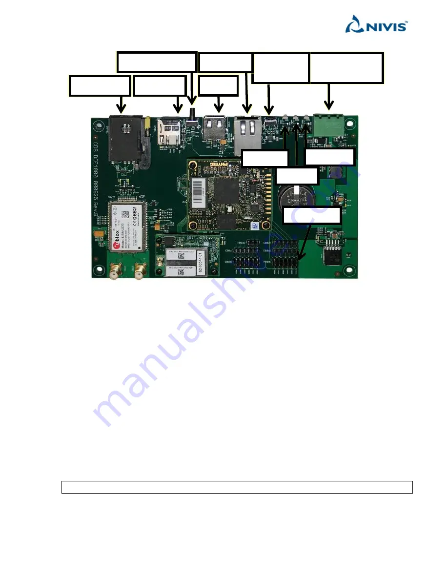
Inside of enclosure, the following LED’s, buttons and connectors are available:
The green connector (1) in the left is for power supply connection.
There are 3 main LEDs on the Titan board next to the power supply connection: “ALARM”, “WAN”, and “CELL”
The other two secondary LEDs are the ETH link/activity LEDs
The “ALARM” LED (2, red) lights solid on when the SD-card is not detected or is malfunctioning.
The “ALARM” LED (2, red) is blinking while the board is in the process of reset to factory defaults.
The “WAN” LED (3, green) lights solid on when there is a NAMT or a browser connected to the Versa Router™
1100 Titan.
The “CELL” LED (4, blue) lights solid on when the cell link is established.
To the left is the RJ-45 connector (6) for WLAN connectivity.
Next there is the USB connector. The USB currently has no functionality for Titan.
Next to the left there is the “Reset to Defaults” button (6). It serves to reset the settings to the factory defaults.
See the following section for additional details.
To the left there is the SD-card holder. It must have a working SD-card at all times.
NOTE
Titan does NOT function without a properly working SD-card
(11) Tamper
(1) Power supply
and detection
(5) Processor
reset
(6) Ethernet
(7) USB
(8) Reset to default
(9) SD-card
(10) SIM card
(2) ALARM
(3) WAN
(4) CELL


