Control System
20
Service Manual – Scrubtec R 253 - RA40
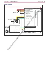
Wiring Diagram
IGNITION KEY (SW1)
FCI DUFLEX (2.54 pitch) 6-way, male pins
FCI DUFLEX (2.54 pitch) 9-way, male pins
Dashboard power
Enabling input
Dashboard
Dashboard serial -
Dashboard power supply -
Electronic board power
Electronic board power supply -
Key electronic board power
Return from USER key
External power supplies -
Display electronic board power
Enabling input from display electronic board
Display electronic board
Display electronic board serial -
Return from steering microswitch
Microprocessor
DASHBOARD
ELECTRONIC
BOARD (EB4)
FUNCTION BOARD (EB1)
SIGNAL CIRCUIT
FUSE (F2)
DISPLAY BOARD (EB2)
J3
J2
J1.5
J1.1
J1.2
J1.3 (+5V)
J1.4
J1.5
J1.6
J1.7
J1.8
J1.9
J1.12
B+
B -
J1.4
J1.3
J1.2
J1.1
J4.1
J4.2
J4.3
J4.4
Enabling from battery charger
Power supply from battery charger
Battery charger enabling power supply
Battery charger data communication
BATTERY CHARGER (CH)
ANTI-SKID
CONTROL
SENSOR (SW4) (SEE THE STEERING SYSTEM CHAPTER)
Key reader power supply circuit
Key Identification
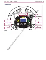
Figure 1
https://harrissupplyind.com - To Order Parts Call 608-268-8080

