Control System
25
Service Manual – Scrubtec R 253 - RA40
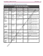
Function Electronic Board (EB1) Alarm Codes (Continues)
Drive system alarms
Alarm on function electronic board - FLASHING YELLOW LED
Alarm code
--------------------------
Description
No.
flashes on
electronic
board
Meaning
Condition
Effect
Service Suggestions
T2
-----------------------
DRIVE MOTOR
OVERLOAD
2
Amperometric
protection
intervention.
Drive system motor
amperage greater than
the parameter (see page
28) “INOM” for more than
the parameter (see page
30) “TMAX”.
Drive blocked.
Check the drive system motor amperage
(this should be around 6-8A without
load and remain below 10/12A during
operation).
T3
-----------------------
RELEASE THE
PEDAL !
3
Pedal not in rest
position when the
electronic board
is turned on.
Voltage on J1.2 of EB2
electronic board above
the value of “DEADL”
parameter.
Drive blocked.
Check that the pedal moves correctly,
lubricating if necessary; check the linkage
and potentiometer.
T4
-----------------------
PEDAL INPUT
FAILURE
4
Incorrect voltage
measured
at the pedal
potentiometer
input.
Voltage on J1.2 of
electronic board EB2
above 6V.
Drive blocked.
1. Check the connection of the
potentiometer to the electronic board.
2. Replace the pedal potentiometer.
T5
-----------------------
HARDWARE
FAILURE
5
Drive system
power section
damage
MOSFET short circuit.
Drive blocked.
1. Check that the cables of the
gearmotor are not short circuited (try
disconnecting the connectors from
contacts M1 and M2) and try starting
the machine and pressing the pedal
again
2. If the alarm persists, replace the
electronic board
T6
-----------------------
DRIVE MOTOR
FAILURE
6
Overcurrent
(motor D.C.)
Drive system motor
amperage greater than
1.5 times the value of the
parameter (see page 28)
“IMAX”.
Drive blocked.
1. Check that the gearmotor cables are
not short circuited
2. Check that the motor of the gearmotor
unit is not short circuited (the
impedance of the motor should be
around 0.6 – 0.8 Ohm)
3. If necessary, replace the gearmotor unit
motor
T7
-----------------------
OVERHEATING
7
Drive system
motor drive
section thermal
cut-out.
The heatsink on the
electronic board has
reached a temperature of
194 °F (90 °C).
Drive blocked.
1. Check the drive system motor
amperage and that the openings of the
electrical compartment are not blocked.
2. If everything is within normal
parameters, this may simply have been
caused by extreme working conditions
such as: ambient temperature over
86 °F (>30 °C), sloping working
sections. Simply leave the system to
cool and turn the machine back on.
T8
-----------------------
ELETTROBRAKE
FAILURE
8
Drive system
motor
electromagnetic
brake failure
Electromagnetic brake
resistance above 1 kΩ.
Drive blocked.
1. Check the electromagnetic brake
connection.
2. Replace the electromagnetic brake.
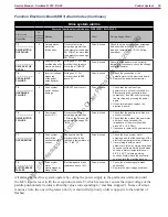
All alarms of the drive system operate by cutting the power supply to the gearmotor unit motor until
the KEY input is reset (with the exception of alarm T3 which is reset as soon as the input voltage of the
paddle potentiometer returns within the values corresponding to “machine stopped”). In case of simul-
taneous errors, the one with greater priority is shown first (priority order is opposite to the number of
flashes).
https://harrissupplyind.com - To Order Parts Call 608-268-8080

