


Wheel System, Traction
211
Service Manual – SC6500
™
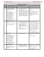
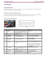
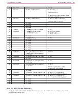
Pin
Wire Color
Circuit
Voltage
10
BLU/BLK
Mode 1 (Curtis Switch 4)
0.003 V Key on
19.2 V Scrub on
0.09 V Scrub on and (“Rabbit” speed
or Traction Control on.)
11
BLK/WHT
Mode 2 (Curtis Switch 5)
0.003 V Traction Control off
19.1 V Traction Control on
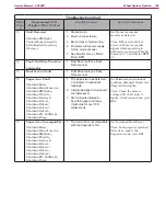
12
Not Used
13
Not Used
14
Not Used
15
VIO/BLK
Throttle POT High (5 V supply)
5.31 V
16
BRN/RED
Throttle POT wiper (Pedal
potentiometer Input)
4.91 V Full Forward
2.72 V Neutral
0.51 V Full Reverse
17
Not Used
18
WHT/BLK
Throttle POT Low
0.21 V
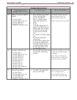
19
Not Used
20
Not Used
21
Not Used
22
Not Used
23
Not Used
24
Not Used
25
VIO/WHT
Unregulated low power +12 V
output. (Power for Programmer
Connector)
12.99 V
26
PINK/RED
Regulated low power +5v output
5.03 V
27
Not Used
28
WHT/ORN
Serial Transmit for Programmer
Connector
0.11 V
29
BLU/GRN
Serial Receive for Programmer
Connector
0.002 V
Momentary jump to 4 V when
programmer is connected
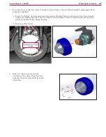
30
Not Used
31
PINK/WHT
Drive Motor Encoder Signal - Phase
A
4.80 V or 0.12 V stationary
2.3 V wheel spinning any speed
32
PINK/BLU
Drive Motor Encoder Signal - Phase
B
4.84 V or 0.12 V stationary
2.3 V wheel spinning any speed
33
Not Used
34
Not Used
35
Not Used
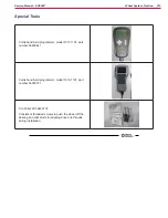
Motor U, V and W Terminal Pair Voltages
• U to V , V to W or W to U- 63 mVAC with stationary motor. 11.8 VAC with wheel off ground and full
forward speed maintained.