


Wheel System, Traction
210
Service Manual – SC6500
™
Specifications
Shop Measurements
Shop measurements are values that were measured on a real machine. While they are not “specifications”,
they can help you recognize normal vs. abnormal.
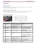
Wheel Drive Controller Voltage Measurements
All voltages are DC unless otherwise stated and were measured with the negative (black) voltmeter lead on
battery negative and the key switch on. Battery voltage was 38.52 V at time of testing.
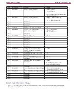
Low Current 35 Pin Connector (X6)
Pin
Wire Color
Circuit
Voltage
1
ORN
Key switch input. Provides logic
power for the controller and power
for the coil drivers.
37.67 V
2
Not Used
3
ORN/RED
Fault (Curtis Driver 4)
34.37 V with no current faults
4
YEL/RED
Direction (Curtis Driver 3)
34.37 V Forward or Stationary
0.004 V Reverse
5
RED/WHT
Motion (Curtis Driver 2)
25.85 V Stationary
0.005 V Moving (Forward or Reverse)
6
BLK/YEL
K7 Main Contactor Driver (Curtis
Driver 1)
37.7 V key on (contactor off)
When seat switch closes, momentary
drop to 1.7 V to turn on contactor.
Then stabilizes at 9.1 V to hold
contactor on.
7
BLK/PINK
Sensor ground reference. (Internal
connection to B-) (Curtis I/O
ground)
0.018 V with motor running
8
TAN/RED
Motor Temperature Sensor (Curtis
Analog 2 or Switch 2)
1.24 V (Room Temp)
12 7 V (open circuit)
9
GRN
Interlock Switch Input (Curtis Switch
3)
37.65 V