background image

VRA53801-R.3609.A

- D6・ LS-50 -

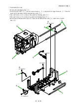
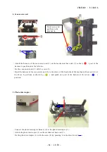
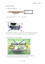
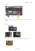
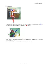
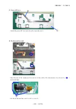
6. AD-FPC, AD retaining plate, AD installing-plate unit

Take out 1 screw (

) and 2 screws (

) to remove the AD-FPC (

).

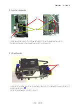
Take out 1 screw (

) to remove the front shield plate (

).

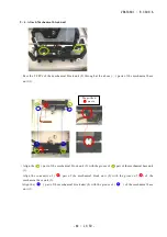
Take out 2 screws (

), then while lifting the AD installing-plate (

) in the direction of (

), remove 

it by pulling in the direction of (

).

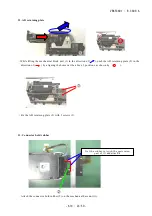
Take out 2 screws (

), and remove the AD installing-plate (

) by pulling in the direction of (

).

>PC-GF20<

*D1-D2505FEx2

*D1-D2008FE

*F1-2608FE1x2

*F1-26080FE1x2

x2

Summary of Contents for COOLSCAN V ED

Page 1: ...VRA53801 R 3609 A 作成承認印 配布許可印 REPAIR MANUAL NIKON CORPORATION Tokyo Japan Recycled paper Printed in Japan January 2004 Copyright c 2004 by Nikon Corporation All Rights Reserved M サービス 計画課 ...

Page 2: ... 20 is operationally compatible with IA 20 S It is possible to insert FH 1 and FH 2 to MA 21 but image processing is different Appropriate film 35 mm film Color monochrome positive negative Slide mount 1 0 mm 3 2 mm in thickness 49 mm 50 8 mm in width Strip film up to 6 frames APS cartridge film Glass microscope slides 26 mm 76 mm 0 8mm 1 5 mm in thickness How to insert Slide mount Insert into MA ...

Page 3: ... 8μm pixels black and white linear CCD Maximum optical resolution 4000dpi Scanning range No of scanning pixels convert at 6 377μm to 1 pixel MA 21 25 1mm 36 8mm 3946 5782 pixels SA 21 25 1mm 38 0mm 3946 5959 pixels IA 20 S 18 6mm 28 4mm 2916 4453 pixels Aperture size MA 21 Aperture of slide mount SA 21 23 4mm 36 0mm IA 20 S 16 1mm 27 4mm FH 3 24 0mm 36 0mm FH G1 23 5mm 36 7mm A D conversion 14 bit...

Page 4: ...N 83 ROC ON 63 GEM ON 112 Revelation ON 109 Scan image enhancer ON 48 All ON 206 APS Posi All OFF 30 APS Nega All OFF 38 8 bits Note Scanning time by USB1 1 ICE4 Scan image enhancer TYP value 35 mm Posi All OFF 78 14 bits ICE4 Scan image enhancer TYP value 35 mm Posi All OFF 142 Interface USB2 0 Hi Speed USB based Data transfer speed Max 480Mb s Power supply Voltage AC100 240V Electrical current c...

Page 5: ...ard unit The main PC can be divided into MCU unit custom IC unit IF Interface unit analog signal processing unit illumination LED driving unit and motor driving unit according to function MCU unit This consists of 16 bit MCU SS assembly Flash memory 128 KB 8 bit SRAM 1 and RESET IC etc and controls entire system including adapters Custom IC unit This performs at 100MHz of the maximum operating fre...

Page 6: ...oards and includes the power supply circuit AC inlets and power supply switch While the input voltage ranges from AC85 to 264V the output voltage is 5V 12 2V and 15 5V 1 6 Connect adapter and feeder to the body Mechanical connections The adapter rails are engaged in the grooves of the AD installing plate on the body side The adapter is pushed from above to the AD installing plate by the spring Whe...

Page 7: ...ctions are made for each color and line 2 3 Shading correction The illumination irregularity and the CCD non uniform sensitivity is corrected digitally per pixel by 16 bit correction coefficient of each color The correctable irregularity non uniformity is 49 98 or under In case the irregularity non uniformity before the correction exceeds 49 98 errors occur The correct coefficient of which charact...

Page 8: ...f the max exposure for each RGB color become 16383 LUT is created based on the characteristic curve which describs the max value of the max exposure and min value of the min exposure of each color Regarding posi films processing the color is decided of the max value of pixels among RGB and the exposure time of RGB is multiplied by uniform scaling factor so that the max value of the color becomes 1...

Page 9: ...anipulates an image such as γ compensation However only about Kodachrome the driver designates the film type Nega films Based on the results of prescan and base density measurement LUT for nega posi conversion is created This creation of LUT is made by the driver software and the body scanner does not make nega posi conversion The processes such as γ compensation CMS compensation tone curve compen...

Page 10: ...ht insufficient light volume of speedlight overexposure 2 14 Resolution and resizing process Maximum optical resolution 4000dpi The body scanner can perform pixel skipping scanning in both main and sub scanning directions Pixel skipping Pitch 1 1 44 corresponding to 4000dpi 90dpi However the scanner does not perform pixel skipping regarding odd number Pitch except the full Pitch The final scan is ...

Page 11: ...etried by changing the illumination LED of AF The illumination LED of AF should be No 1 B No 2 I No 3 G or R To prevent wrong focus on borderlines of images it should be confirmed that the max and min values of contrast meet the following condition Max value Min value 1920 14 bits If the above condition is not met or the contrast cannot be calculated it is retried by moving the CCD in sub scanning...

Page 12: ...mber of lines 2 22 SA lock mechanism SA 21 has the mechanism of mechanical lock in order to prohibit the removal of the adapter from the body scanner with films being inserted If films are inserted the locking plate is protruded from the adapter and it engages with holes of the body scanner 2 23 Transport lock When the scanner is transported the security against shocks or jolts is ensured by setti...

Page 13: ...w then take out 4 screws Take out 6 screws Pull the top cover backwards to remove it from the body unit Take out 4 screws and 2 screws to remove the under panel Unhook the 2 upper and lower claws of the front panel to remove it from the body unit ICE 4 本体部 D1 D2505FEx4 D1 D2505FCx2 D1 D2505FEx4 D1 D2505FCx6 ツメ ツメ Claw Claw ...

Page 14: ...ply unit Take out 1 screw 3 screws and 1 screw to remove the power supply unit Remove the PS insulating plate Remove the harness of the lid release SW from the main PCB Take out the screw then remove the film gate assembly while pressing it in the direction of D1 D4006FE H1 20060FE D1 D2505FEx3 D1 D2505FC D1 D2505FC ...

Page 15: ... LED harness Take out the screw to remove the core holder Remove the harness of photo interrupter the harness of scan motor and the AF motor FPC Take out 1 screw and 8 sccrews Open the main PCB slightly and remove the CCD FPC and the ferrite core Remove the connector shield D1 D2508FFx8 D1 A2005FE F1 26080FE1 Body unit ...

Page 16: ...p chassis Film rail unit Take out 4 screws to remove the top chassis Take out 2 screws to remove the film rails Take out 2 screws to remove the film rail plate D1 D2508FFx2 H1 20060FE P C G F 2 0 D1 D2505FEx4 D1 D2505FEx2 D1 D2505FE ...

Page 17: ...in chassis unit Take out 2 screws and 1 screw and 1 screw Displace the mechanical block unit from the main chassis in the direction of and remove it by lifting in the direction of A B S P C G F 2 0 D1 D2508FFx2 D1 D2508FF D1 D2505FE ...

Page 18: ...D FPC Take out 1 screw to remove the front shield plate Take out 2 screws then while lifting the AD installing plate in the direction of remove it by pulling in the direction of Take out 2 screws and remove the AD installing plate by pulling in the direction of P C G F 2 0 D1 D2505FEx2 D1 D2008FE F1 2608FE1x2 F1 26080FE1x2 x2 ...

Page 19: ...arness from the hooks on the backside of the mechanical base unit Take out 2 screws to remove the guide bar retaining plate Take out 2 screws to remove 2 guide bar retaining plates Detach the mechanical block unit from the mechanical base unit and remove 2 guide bars P C G F 2 0 H1 20060FEx2 F1 30060FE1 F1 30060FE1x2 H1 20060FEx2 H1 20060FE ...

Page 20: ...ecessary to adjust the illumination irregularity Refer to Page A27 for how to adjust and also refer to Page 29 for the inspection software and necessary tools Take out 4 screws and disassemble the mechanical block unit and the illumination base assembly P C G F 2 0 D1 A2005FEx4 H1 20060FEx2 F1 30060FE1x2 H1 17030FE ...

Page 21: ...ed through of LED block unit 2 put it in through 〇 part of the illuminate base assembly 1 to be pinched 2 AF unit Attach the AF unit 2 on the scan block unit 1 Fold the FPC of the AF unit 2 along each line of 2 parts Fix the motor unit of the AF unit 2 with 2 screws 3 Check if there is no dust attached on the sensor of 〇 part Put the inner sensor of 〇 part into the hole of scan block unit 1 Fix th...

Page 22: ...ide of the scan block unit 1 at the above 〇 position 3 Lens cover Check if there is no dust on the whole lens cover 2 Attach the lens cover on the mechanical body unit 1 by entering the bosses into the 2 concavities of 〇 parts and the 2 holes of 〇 parts Hook here Hole 凹 ...

Page 23: ...he scan motor unit 2 to the claws of the backside of the mechanical base unit 1 at the above 4 positions as shown by 〇 and pinch one part of the harness at the above 〇 position 5 Photo interrupter Connect the photo interrupter harness 2 to the photo interrupter 1 Attach the photo interrupter 1 on the mechanical base unit 3 Fix the photo interrupter 1 with the screw 4 by pressing it in the directio...

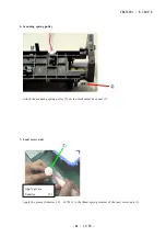
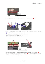
Page 24: ...0 6 Scanning spring pulley Attach the scanning spring pulley 2 on the mechanical base unit 1 7 Lead screw unit Apply the grease Sumitec 331 J67033 to the thrust spring retainer of the lead screw unit 1 Apply grease Sumitec 331 ...

Page 25: ...own by 〇 and attach them Attach the lead screw receiver 3 on the mechanical base unit 1 Fix the lead screw receiver 3 with the screw 4 Apply the grease Sumitec 331 J67033 to the shafts of the lead screw unit 5 as shown by 〇 Apply the rice grain sized grease Sumitec 331 J67033 to 〇 part between the motor gear of the mechanical base unit 6 and the lead screw unit Apply grease Sumitec 331 Apply greas...

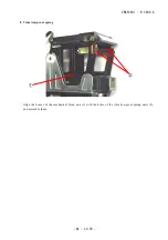
Page 26: ...VRA53801 R 3609 A A6 LS 50 8 Vibration proof spring Align the bosses of the mechanical block unit 1 with the holes of the vibration proof spring units 2 and assemble them ...

Page 27: ...ut grease through on the A side of the mechanical block unit 3 Pass the guide bar 2 with grease through on the B side of the mechanical block unit 3 9 3 Attach Scanning vibration proof spring Attach the scanning vibration proof spring unit 2 on the mechanical block unit 1 Fix the scanning vibration proof spring unit 2 with the screw 3 Grease applied area Apply grease Sumitec 331 A B ...

Page 28: ...anical base unit 1 Align the 〇 part of the mechanical block unit 2 with the groove of 〇 part of the mechanical base unit 1 Align the convexity of 〇 part of the mechanical block unit 2 with the groove of 〇 of the mechanical base unit 1 Align the 〇 part of the mechanical block unit 2 with the groove of 〇 of the mechanical base unit 1 Magnified parts ...

Page 29: ...ar plate B 3 on the mechanical base unit 1 Fix the guide bar plate A 2 and guide bar plate B 3 with 4 screws 4 11 AD installing plate Attach the AD installing plate 2 on the mechanical base unit 1 by aligning the bosses at the above 2 positions as shown by 〇 Fix the AD installing plate 2 with 2 screws 3 ...

Page 30: ...te While lifting the mechanical block unit 1 in the direction of push the AD retaining plate 2 in the direction of by aligning the bosses at the above 2 positions as shown by 〇 Fix the AD retaining plate 2 with 2 screws 3 13 Connector hold rubber Attach the connector hold rubber 2 on the mechanical base unit 1 ...

Page 31: ... the FPC of the AF unit 2 to the claws of the mechanical base unit 1 at the above 4 parts as shown by 〇 15 AD FPC Attach the AD FPC 2 to the mechanical base unit 1 by passing the claws through the holes Fix the AD FPC 2 with 2 screws 3 Backside ...

Page 32: ...nit 1 by aligning the bosses as shown by 〇 Fix the film rail plate with 2 screws 3 at the above 〇 positions Enter the boss of the sensor of the AD FPC unit 4 in the notch of the mechanical base unit 1 and fix them with the screw 5 Check if the head of the sensor of the AD FPC unit 4 operates smoothly ...

Page 33: ... lever Attach the power SW lever unit 2 on the main chassis 1 18 Mechanical base unit Hook the claw of the mechanical base unit 2 to the notch of the main chassis 1 as shown by 〇 and attach them Fix the mechanical base unit 2 with 3 screws 3 ...

Page 34: ... film rails by aligning the bosses of the upper film rail 1 and lower film rail 2 Attach the rail perforation sensor unit 2 on the film rail 1 with the screw 3 Put the harness of the rail perforation unit 2 in through 〇 part of the film rail to be pinched ...

Page 35: ... hole of the mechanical base unit 1 and assemble them Fix the film rails 2 with 2 screws 3 21 Film gate Attach the film gate unit 2 on the mechanical base unit 1 Fix the film gate unit 2 with the screw 3 Put the harness of the film gate unit 2 in through 〇 part of the mechanical base unit 1 to be pinched ...

Page 36: ...cal base unit 1 and also hook part of the spring to 〇 part of the scanning spring pulley 3 23 Light guide Attach the light guide 2 to the top chassis 1 by aligning the bosses at the above 2 positions as shown by 〇 Fix the light guide 2 with the screw 3 Place the tip of spring downwards to prevent the spring come off ...

Page 37: ...1 R 3609 A A17 LS 50 24 Top chassis Attach the top chassis 2 on the mechanical base unit 1 by aligning the bosses at 4 positions as shown by 〇 Fix the top chassis 2 with 4 screws 3 in the order from 3 1 to 3 4 ...

Page 38: ...ld plate A 2 to the main PCB unit 1 until it clicks Connect the power supply harness 3 to the main PCB unit 1 Pull out the locks at the above 4 parts as shown by 〇 of each connector 25 2 Attach CCD FPC Insert the CCD FPC 1 into the ferrite core 2 Connect the CCD FPC to the main PCB unit 3 Pull out ...

Page 39: ... of and fix it with 8 screws 3 Fix the connector shield plate A 5 with the screw 4 26 Attach AF FPC Scan motor harness Fold the AF FPC 1 along the folding marks as shown by 〇 Connect the AF FPC 1 to the connector of the main PCB unit 2 Connect the harness 4 lines of the scan motor unit 3 and the harness 3 lines of the photo interrupter 4 to the main PCB unit 2 ...

Page 40: ... the core holder 1 into the groove of the mechanical base unit 4 Fix the core holder 1 from above with the screw 3 28 LED harness Connect the LED harness to 〇 part of the main PCB unit 1 Put the LED harness 2 in 〇 part to be pinched Be careful NOT to pinch the LED harness 2 at the position indicated by ...

Page 41: ...d the harness 2 lines of the lid release SW 3 to the main PCB unit 1 as shown by 〇 30 PS insulating plate Make a valley fold along the line of of the PS insulating plate 1 and frame it by hooking at 〇 part Push the PS insulating plate 1 in the chassis 2 downwards as shown by and assemble them Push the insulating plate in downwards ...

Page 42: ...e power supply harness 2 to the power supply unit 1 Align the convexity of the SW of the power supply unit 4 with the concavity of the power supply SW bar 3 and assemble them Fix the power supply unit 1 with 3 screws 4 and 1 screw 5 Fix the power supply unit 1 with the screw 6 ...

Page 43: ...y harness 2 and connect them to the connectors of the main PCB unit 3 respectively 33 Front shield plate Align the bosses of the mechanical base unit 1 with the holes of the front shield plate 2 at the positions as shown by 〇 to assemble them Fix the front shield plate 2 with 2 screws 3 and 1 screw 4 ...

Page 44: ... groove of the chassis 3 and assemble them 35 Under panel Fix the rear side of the under panel 1 with 2 screws 2 Reverse the body unit 3 and attach the under panel 1 to the front panel unit 4 by pressing it in the direction of and aligning the bosses at 4 positions as shown by 〇 Fix the bottom of the under panel 1 with 4 screws 5 in the order from 4 1 to 4 4 ...

Page 45: ...09 A A25 LS 50 36 Top cover Reverse the body unit 1 and while sliding in the direction of put it into the top cover 2 Lay the body unit 1 along and tighten 4 screws 3 Lay the body unit 1 along and tighten 4 screws 4 ...

Page 46: ...along line on the front panel unit 1 and attach it by pressing on from the top to side faces Enter the bosses of the rubber foot for front 4 in the bottom grooves of the body unit 3 Attach the rubber foot for rear 6 at 3 5 mm distance from the backmost edge of the body unit 5 ...

Page 47: ...65050A in Japanese J65050B in English Refer to Page on and after A29 for the details of the inspection software 3 Select Run from the main menu and Illumination Irregularity from the pulldown menu 4 The CCD output wave is indicated as below In case of LS 50ED only 1 line data is displayed The waveform is updated every a few seconds 5 Adjust so that the amplitude of the CCD output waveform 1 gets m...

Page 48: ...09 A A28 LS 50 6 Loosen 4 screws 5 of the illumination base assembly 4 and by adjusting the position of the illumination base assembly 4 make an adjustment to meet the standard of 5 7 Tighten 4 screws 5 to complete ...

Page 49: ...h OS CPU Pentium Ⅲ 700MHz or more RAM 256MB or more 3 Inspection details 1 Initialization Check the firmware version 2 Illumination irregularity Check for the raw data of the CCD with shading OFF in the standard range 3 Shading Check for the read in data of the CCD waveform with shading ON in the standard range 4 Noise inspection By performing prescanning operation check if the operating sound has...

Page 50: ... the leak rate of unnecessary light that is included in R LED Whenever the main PCB or parts of optical system are replaced it is necessary to rewrite the compensation data 7 Color reproduction positive Read the positive macbeth chart by scanner and check the color reproduction of each color 8 Log record As for the log numbers the number of times for scanning for AF operations for thumb nails for ...

Page 51: ...s the compressed file and store the following 7 files in any folder Connect LS 5000ED to PC and turn the power ON Insert the adjustment and inspection glass chart J61187 Double click the file S10S05Sv exe to start the inspection software Click Service mode LS 5000ED or Service mode LS 50ED ...

Page 52: ...re Select Setting on the main menu and choose Compensation of the reading position of inspection adapter from the pulldown menu Input adapter No corrective value in X direction corrective value in Y direction and corrective value in Z direction that are attached on the inspection chart J61187 then click OK ...

Page 53: ...0 4 3 Procedure for inspection 1 Check the firmware version Select Run on the main menu then choose Initialize and INQUIRY from the pulldown menus in order to check the firmware version Click OK after the check Firmware version ...

Page 54: ... folder Select Setting on the main menu and choose Set Parameters from the pulldown menu Click Reference to designate the folder where the firmware was saved in Write the firmware name in Inquiry Click Apply Click OK Select Run on the main menu and choose Download from the pulldown menu ...

Page 55: ...VRA53801 R 3609 A A35 LS 50 Click Start to upgrade the firmware When OK is displayed in Result the upgrading is completed ...

Page 56: ...Inspection result on Illumination irregularity In the above screen the CCD sensor addresses are allocated on the horizontal axis If foreign matter such as dust enters between the LED illuminator and CCD sensor the waveform of the address shifts significantly downward so dust etc can be recognized by visual check Illumination irregularity Standard 42 or less In case of NG clean the optical system ...

Page 57: ... File on the main menu and choose Scan Image from the pulldown menu In Select the Chart choose No chart and tick the box of ON OFF of SD Then click OK The scanning starts automatically Select Run on the main menu then choose Shading and Saturation from the pulldown menus ...

Page 58: ...rregularity is not within standard or there is problem with the shading compensation circuit on the main PCB In the first case clean the optical system and adjust the illumination irregularity or replace the illumination LED unit In the other case replace the main PCB Select Run on the main menu then choose Shading and Compensation between Adjacent pixels from the pulldown menus Inspection result ...

Page 59: ...50 4 Noise inspection Select Run and choose Noise Check While Scanning operation from the pulldown menu When OK is clicked the scanning starts automatically Check if there is no problem with the operating sounds during scanning ...

Page 60: ...t 4 corners with the mouse for adjustment so that the alignment mark black circle can be placed enough inside this frame The position that was adjusted once is automatically stored in the initial file So unless the film slips significantly from the mount nor the scanning position of the scanner largely changes it is NOT necessary to make an adjustment afterwards Adjust so that the alignment mark b...

Page 61: ...ase of NG Replace the mecha block unit Inspection result on scanning position accuracy Color registration Select Run on the main menu then choose Mechanical Precision Test and Color Registration from the pulldown menus In case of NG Clean the optical system and clean apply grease on the carriage advance mechanism or replace the mecha block unit Inspection result on color registration ...

Page 62: ... menu then choose Mechanical Precision Test and Aspect Ratio from the pulldown menus In case of NG Replace the mecha block unit Main Sub scan perpendicularity Select Run on the main menu then choose Mechanical Precision Test and Main Sub scan Perpendicularity from the pulldown menus In case of NG Replace the mecha block unit Inspection result on Main Sub scan perpendicularity Inspection result on ...

Page 63: ...f NG Clean apply grease on the AF mechanism unit and clean the optical system or replace the mecha block unit Flare Select Run on the main menu then choose Mechanical Precision Test and Flare from the pulldown menus In case of NG Clean the optical system and inspect the AF mechanism unit Inspection result on MTF Inspection result on Flare ...

Page 64: ...ion position Select Run on the main menu and choose AF Focal Precision Position from the pulldown menu Then the AF operates automatically In case of NG Clean the optical system and inspect the AF mechanism unit Inspection result on AF focal precision position ...

Page 65: ...n Image from the pulldown menu Then select IR Pass Filter and click OK Do NOT insert MA021 and IR pass filter J63088 yet Scanner When the following message is indicated insert MA 21 into the scanner Then wait until the green LED changes from blinking to lightening for about 30 seconds and click OK Do NOT insert IR pass filter J63088 yet MA 21 ...

Page 66: ...VRA53801 R 3609 A A46 LS 50 When the following message is indicated insert IR pass filter J63088 into MA 21 When OK is clicked the scanning starts MA 21 IR pass filter J63088 ...

Page 67: ...After replacing the parts perform the above IR Leakage Test IR pass filter Record each data of inspection result Leak_g Leak_s Leak_k then rewrite the compensation data according to the instruction of the next page Select Run on the main menu and IR Leakage Test IR pass filter from the pulldown menu In case of NG LED malfunction should be considered ...

Page 68: ...data according to the following instrucition Select Run on the main menu then choose IR Leakage Intensity and Write from the pulldown menus Input each data Leak_g Leak_s Leak_k that was recorded in then click OK After replacing parts perform IR Leakage Test IR pass filter from page A17 to A19 Record each data on inspection results Leak_g Leak_s Leak_k ...

Page 69: ...VRA53801 R 3609 A A49 LS 50 Click OK After completing writing click OK to go back to the main menu ...

Page 70: ...rom the scanner Insert MA 21 into the scanner Insert the posi chart J61189 and check if the green LED changes from blinking to lightening Select File on the main menu and Scan Image from the pulldown menu Then choose Posi Chart and click OK the scanning starts automatically Posi chart J61189 MA 21 ...

Page 71: ...ptical system Inspection result on Positive color reproduction When the scanned image is displayed on the monitor drag the alignment detection frame black square frame with the mouse for adjustment so that the alignment mark black circle can be placed enough inside this frame Adjust the both right and left alignment marks Alignment mark Alignment detection frame ...

Page 72: ...When Run Log Load and File are selected the saved log data on PC is called up When Run Log and Clear are selected the log data in the flash memory on the main PCB is cleared Clear The log data in the flash memory on the main PCB is cleared deleted Write The saved log data is written in the flash memory Save The log data is saved on PC ...

Page 73: ...CB Initialize WB data when the LED is replaced or parts of optical system is cleaned Write The WB data is written When the main PCB unit is replaced be sure to perform Read before the replacement and make note of values of WB data Then after the replacement write the noted values Read The WB data that was written in the flash memory is read i e WB data at shipment or when the LED is replaced for r...

Page 74: ...VRA53801 R 3609 A LS 50 ELECTRIC CONTENTS BLOCK DIAGRAM E1 WIRING E2 MAIN PCB 1 E3 MAIN PCB 2 E4 MAIN PCB 3 E5 MAIN PCB 4 E6 MAIN PCB 5 E7 ...

Page 75: ...0V 12 2V 電源 ASSY POWER SUPPLY ASSY MAIN 基板部組 MAIN ASSY MICRO CONTROLL UNIT 12 5MHz CLK FLASH 128KB SRAM 25MHz CLK 25MHz CLK 係数メモリ COEFFICIENT MEMORY 128KB SRAM 128KB SRAM 32KB SRAM 32KB SRAM USB 2 0 12MHz CLK 12MHz CLK 12MHz CLK RESET IC TEST I O 12 5MHz CLK BUFFER MEMORY CCD 部組 CCD BOARD ASSY C C D 2 778MHz CLK 14bit A D 2 778MHz CLK FINE 1 2 COARSE 8bit D A BLACK LEVEL COMPENSATION 黒レベル補正 CDS 2 ...

Page 76: ... 2 A AF FPC assy 3 B AF FPC assy 4 B AF FPC assy 5 Tr_C AF FPC assy 6 LED_C AF FPC assy 7 LED_A AF FPC assy 8 Tr_E LED block assy 1 COM LED block assy 2 LEDR LED block assy 3 LEDI LED block assy 4 LEDB LED block assy 5 LEDG Photo interrupter harness Photo interrupter CCD boad assy S0005 Mecha block assy S0005 Illumination base assy LED block assy AF assy AF FPC assy Scan motor assy Scan motor ...

Page 77: ...VRA53801 R 3609 A ー E3 LS 50 ー メイン基板 1 Main PCB 1 ...

Page 78: ...VRA53801 R 3609 A ー E4 LS 50 ー メイン基板 2 Main PCB 2 ...

Page 79: ...VRA53801 R 3609 A ー E5 LS 50 ー メイン基板 3 Main PCB 3 ...

Page 80: ...VRA53801 R 3609 A ー E6 LS 50 ー メイン基板 4 Main PCB 4 ...

Page 81: ...VRA53801 R 3609 A ー E7 LS 50 ー メイン基板 5 Main PCB 5 ...

Page 82: ...VRA53801 R 3609 A LS 50 The contents of inspection standards and tools 1 Inspection standards R1 R 6 2 tools T1 ...

Page 83: ...s in black areas 48 6 db or more for each RGBI Light volume The following conditions of WB time for RGBI should be met Conditions WB time RGBI only R 30μs G B I 25μs Color Positive 3 colors R 1 995 G 1 995 B 1 995 4 366 ms Color Positive 4 colors R 1 995 G 1 995 B 1 995 I 1 122 2 8 690 ms Color Negative 3 colors R 1 995 G 3 981 B 7 943 8 863 ms Color Negative 4 colors R 1 995 G 3 981 B 7 943 WBI 1...

Page 84: ...ain scannig direction 0 70 mm or less Sub scanning direction 1 26 mm or less Trimming misalignment 1 pixel or less Main scanning magnification 1 254 times 1 83 or less Horizontal to vertical ratio Aspect ratio 36 87 Sub 25 17 Main 2 or less Main sub scan perpendicularity 90 0 35 Sub scan parallelism Total area 6 pixels or less within the range of 36 87 mm Between adjacent pixels 1 pixel or less fo...

Page 85: ...more IR color MTF of 17 5 line mm chart area should be 20 or more Color registration Among RGB 1 pixel or less IR color Scanning misalignment from RGB image should be 4 pixels or less Flare Data spread in black and white boundary areas should be 3 92 10 255 LSB or less Ghost image Data spread in black areas should be 3 92 10 255 LSB or less Color reproduction Positive film Average ΔE of 24 patches...

Page 86: ...ec or less Thumbnail time SA 21 30 sec or less IA 20 S 25 frames winding time 19 sec or less 25 frames thumbnail time 120 sec or less 40 frames winding time 25 sec or less 40 frames thumbnail time 200 sec or less 6 Image quality performance 2 Negative film reproducible density range Under conditions of CMS off γ 1 and 14 bits output images should be scanned within the range from the min value is 0...

Page 87: ...eaking No streaks in both main and sub scanning directions Grain roughness Indistinctive No significant difference from the traditional models Irregular color Color difference ΔE should be 5 or less Influence of outside light No influence 7 Operating sounds No significant abnormal sounds with 55 dB or less at a 1 m distance away 8 Status indication BUSY 0 635Hz 1 of blinking frequency ERROR 5Hz 1 ...

Page 88: ...VRA53801 R 3609 A R6 LS 50 10 Electric power consumption AC100V 50 60Hz 0 33A or less 20W or less AC240V 50 60Hz 0 22A or less 20W or less ...

Page 89: ...VRA538001 R 3609 A T1 LS 50 2 工具一覧表 Tool List 新規工具 New tool J63088 IR パスフィルター IR pass filter J65050A J65050B ...

Reviews: